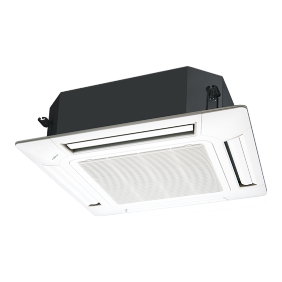
AirStage AUUB18TLAV Panduan Instalasi - Halaman 5
Jelajahi secara online atau unduh pdf Panduan Instalasi untuk Pendingin Udara AirStage AUUB18TLAV. AirStage AUUB18TLAV 17 halaman. Indoor unit (cassette type)

• Distribution ducts and fresh air inlet positions.
Distribution duct connecting port
Distribution duct connecting port
• Detailed diagram of distribution duct connecting port (4 sides)
3-15/16 (100)
3-1/4 (83)
13-7/8 (352)
•
Fresh air inlet position
9-13/16 (250)
Ø 3-7/16 (88)
Burling hole pitch
Note:
Conduct proper insulation when connecting the distribution ducts and fresh air inlet.
Insulation
Fresh air inlet position
* When sucking in the fresh air, please detach the insulation affi xed to the drain pan.
(2) Setting the positions of hanging bolt and ceiling opening.
• Use an installation template (packaging top surface) to set the positions of the hanging
bolt and ceiling opening and drill holes.
(3) Hanging structure.
• Select a strong structure for the hanging location.
• If necessary, reinforce the hanging bolt with quakeproof columnar support material to
prevent shaking.
• Use hanging bolts of M8 to M10.
Fresh air inlet position
Unit: in. (mm)
3-15/16 (100)
3-1/4 (83)
Cut out
10 × Ø 1/8 (2.5) hole
Ø 2-3/4 (70)
Cut out
4 × Ø 1/8 (2.5) hole
3.3.2. Hanging preparations
• Firmly fasten the hanging bolts as shown in the fi gure or by another method.
• Install the hanging bolts at a place where they would be capable of holding a weight of
at least 110 lbf (490 N) per bolt.
Hole-in anchor
Hole-in plug Concrete
Hanging bolt M10
(Field supply)
3.3.3. Body installation
(1) Install the attached washer and nut (prepared on site) onto the hanging bolt.
(2) Hook the body onto the hanging bolt.
(3) Adjust the dimensions of the ceiling surface from the body.
After installing the cassette grille, you can make fi ne adjustment of the height of the
body. For details, refer to the installation manual of the cassette grille.
WARNING
Perform fi nal tightening by tightening the double nut fi rmly.
Be sure to install the body horizontally and adjust the height below the body and the
ceiling surface properly.
(Accessories)
Washer
(Accessories)
Washer
(10 to 15)
3/8 to 9/16
3.3.4. Leveling
• Using a level, or vinyl hose fi lled with water, fi ne adjust so that the body is level.
• Inclined installation so as the drain pipe side is higher may cause a malfunction of the
fl oat switch, and may cause water leakage.
Vinyl hoses
Insert
(Field supply)
Unit: in. (mm)
Hanging bolt
(Field supply)
Nut A
1-3/16 (30) or more
After installing the body,
tighten the nuts.
Nut B (Field supply)
(Double nut)
Drain pipe
En-4
