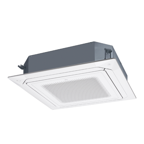
AirStage AUXM018GLEH Panduan Instalasi - Halaman 13
Jelajahi secara online atau unduh pdf Panduan Instalasi untuk Pendingin Udara AirStage AUXM018GLEH. AirStage AUXM018GLEH 13 halaman.

11. ERROR CODES
If you use a wired type remote controller, error codes will appear on the remote controller
display. If you use a wireless remote controller, the lamp on the photodetector unit will
output error codes by way of blinking patterns. See the lamp blinking patterns and error
codes in the table below.
Error indications
OPERATION
TIMER lamp
FILTER lamp
lamp (green)
(orange)
(red)
(1)
(2)
(1)
(4)
(1)
(6)
(2)
(6)
(2)
(9)
(3)
(1)
(3)
(2)
(3)
(10)
(4)
(1)
(4)
(2)
(4)
(4)
(5)
(1)
(5)
(2)
(5)
(3)
(9)
(15)
(10)
(8)
(13)
(1)
Display mode
: 0.5 s ON / 0.5 s OFF
: 0.1 s ON / 0.1 s OFF
( ) : Number of flashing
Wired Remote Controller Display
UTY-RNR*Z* (2-wire type)
Error icon
Touch the [Status].
Touch the [Error Information].
2-digit numbers are corresponding to
the error code in the preceding table.
For more information, refer to the installation manual of the remote controller.
UTY-RLR* (2-wire type)
Error icon
For more information, refer to the installation manual of the remote controller.
Wired remote
controller
Error contents
error code
Remote controller communi-
cation error
Network communication
error
Peripheral unit communica-
tion error
Indoor unit address setting
error
Connection unit number er-
ror in wired remote controller
system
Indoor unit power supply
abnormal
Indoor unit main PCB error
Indoor unit communication
circuit (wired remote control-
ler) error
Indoor unit room temp.
thermistor error
Indoor unit heat ex. temp.
thermistor error
Human sensor error
Indoor unit fan motor 1 error
Indoor unit coil (expansion
valve) error
Indoor unit water drain
abnormal
Outdoor unit miscellaneous
error
Poor refrigerant circulation
RB unit error
Touch the [Next Page] (or [previous page])
to switch to other indoor unit information.
Error code
En-12
