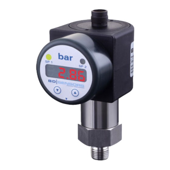
BD Sensors DS 200 Panduan Pengoperasian - Halaman 3
Jelajahi secara online atau unduh pdf Panduan Pengoperasian untuk Beralih BD Sensors DS 200. BD Sensors DS 200 3 halaman. Electronic pressure gauge
Juga untuk BD Sensors DS 200: Petunjuk Pemasangan (2 halaman)
3-wire-system (current / voltage)
p
supply +
supply –
A/V
R
signal +
L
R
contact 1
L
contact 2
contact 3
I/U
contact 4
5. Commissioning
Danger of death from airborne parts,
leaking fluid, electric shock
-
Operate the device only within the
DANGER
specification! (according to data sheet)
The device has been installed properly.
The device does not have any visible defect.
6. Operation
6.1 Control and display elements
LED
LED
unit
contact 1
contact 2
4-digit seven-
segment display
▼-button
▲-button
Fig. 3 Touch pad (example with two contacts)
The device has, according to the order max. four LEDs which
are allocated to the resp. contacts. The LEDs will light up when
the respective set point has been reached and the contact is
active. The display of the measured value as well as the
configuration of the individual parameters occurs menu-driven
via the seven-segment display.
Button functions
• move forward in the menu system
(beginning with menu 1)
• increase the displayed value
note: increase the counting speed by
keeping the button pushed for more than
5 second
• move backwards in the menu system
(beginning with the last menu)
• decrease the displayed value
note: increase the counting speed: keep
the button pushed for more than 5 second
confirm the menu items and set values by
pushing both buttons simultaneously
execution of configuration:
- set the desired menu item by pushing the ▲- or ▼-button
- activate the set menu item by pushing both buttons
simultaneously
- set the desired value or select one of the offered settings by
using the ▲- or ▼-button
- store / confirm the set value/selected setting and exit the
menu by pushing both buttons simultaneously
6.2 Configuration
The menu system is a closed system allowing you to scroll both
forward and backward through the individual set-up menus to
navigate to the desired setting item. All settings are permanently
stored in an EEPROM and therefore available again even after
disconnecting from the supply voltage. The structure of the
menu system is the same for all types of devices, regardless of
the number of contacts. However, they only differ by the number
of menus. Following figure and the menu list shows all possible
menus. On devices with 3-wire output 4 ... 20 mA and
0 ... 20 mA, the menus ZP and EP have special functions. The
menu DP is not applied, as the decimal point is already factory
set during production.
Please follow the manual meticulously and remember that
changes of the adjustable parameters (switch-on point, switch-
off point, etc.) become only effective after pushing both buttons
simultaneously and leaving the menu item.
6.3 Password system
To avoid a configuration by unauthorized persons, the possibility
is given to lock the device by an access protection. More
information is given in menu 1 of the menu list.
6.4 Configuration example of the analogue output for
4 ... 20 mA / 3-wire adjustable
By the menus ZP and EP, the analogue output can be
configured. In the following, the function of these menus shall be
made clear by an example. Assuming you have a device with a
nominal pressure range 0 ... 400 bar by factory the following
performance is set:
0 bar = 4.00 mA
200 bar = 12.00 mA
400 bar = 20 mA
If you change the value in the me nu ZP from 0 to 20 and the
value in the menu EP from 400 to 300, the following
performance will appear:
20 bar = 4.00 mA
160 bar = 12.00 mA
300 bar = 20 mA
The values of ZP and EP are adjustable up to 1:5 of the nominal
pressure range.
6.5. Description of hysteresis and compare mode
To invert the respective modes, you have to exchange the
values for the switch-on and switch-off points.
Fig. 4 Compare mode
Fig. 5 Compare mode
inverted
Fig. 6 Hysteresis mode
Fig. 7 Hysteresis mode
inverted
6.6 Menu list
button functions are well known (see "6.1 Control and display elements")
menu 1 – access protection
V
S
PAon
password active
PAof
password inactive
default setting for the password is "0005"; modification of the password is described in special menu 4
menu 2 – set decimal point position
for devices with 3-wire output 4 ... 20 mA and 0 ... 20 mA the decimal point was already set during production
R
menu 2a – indication of the starting point, which was defined with the order (only 3-wire adjustable)
L
no configuration is possible
R
L
menu 2b – indication of the end point, which was defined with the order (only 3-wire adjustable)
no configuration is possible
menus 3 and 4 – set zero point / end point
the device has been configured correctly before delivery, so a later setting of a 2-wire device is only necessary, if a differing
displayed value is desired (e. g. 0 ... 100 %)
For devices with 3-wire output 4 ... 20 mA and 0 ... 20 mA this menu has a different meaning: The configuration of the zero
point causes a changing of the analogue output, whereas the display value remains unchanged. (zero and end point can be
configured within the limits of the nominal pressure range, according to the manufacturing label); for more information see
"5.4 Configuration example of the analogue output for 3-wire-devices"
menu 5 – set damping
this function allows getting a constant display value although the measuring values may vary considerably; the time constant
for a simulated low-pass filter can be set (0.3 up to 30 sec permissible)
menu 6 – exceeding message
set "on" or "off"
menus 7, 9, 11 and 13 – set switch-on points
set the particular values, for the activation of contact 1 (S1on) up to 4 (S4on)
menus 8, 10, 12 and 14 – set switch-off points
set the particular values, for the deactivation of contact 1 (S1oF) up to 4 (S4oF)
menus 15 up to 18 – select hysteresis or compare mode
select the hysteresis mode (HY 1 up to HY 4) or compare mode (CP 1 up to CP 4) for the contacts 1 up to 4
(no. corresponds to the contact)
compare "6.5. Description of hysteresis and compare mode"
menus 19, 21, 23 and 25 – set switch-on delay
set the particular value of the switch-on delay after reaching switch-on point 1 (d1on) up to 4 (d4on)
(0 up to 100 sec permissible)
menus 20, 22, 24 and 26 – set switch-off delay
set the particular value of the delay after reaching the switch-off point 1 (d1oF) up to 4 (d4oF)
(0 up to 100 sec permissible)
menus 27 and 28 – maximum / minimum pressure display
view high pressure (HIPr) or low pressure (LoPr) during the measurement process
(the value will not remain stored if the power supply is interrupted)
to erase: push both buttons again within one second
menu 29– measured value update (display)
set the length of the update cycles for the display (0.0 up to 10 sec permissible)
menus 30 up to 33 – simulate contacts (only 4 ... 20 mA / 3-wire adjustable)
with the ▲- or ▼-button the contacts 1 (tES1) up to 4 (tES4) can be activated or deactivated
menu 34 – simulate analogue output (only 4 ... 20 mA / 3-wire adjustable)
select one of the following settings: "oi 4" (4 mA or 2 V), "oi12" (12 mA or 6 V) and "oi20" (20 mA or 10 V)
menu 35 – error signal definition (only 4 ... 20 mA / 3-wire adjustable)
set the desired error signal (this is given out in case of a defect); permissible settings are "OFF" (no error signal output),
"C 0" (0 mA or 0 V), "C L0" (3.5 mA or 1.75 V) and "C HI" (23 mA or 11.5 V)
an output of the error signal is only given when menu 6 is set on "on"
menu 36 –offset compensation / position correction (only 4 ... 20 mA / 3-wire adjustable)
confirm menu item "P0SI"; if offset ≠ ambient pressure it is necessary to place the device under pressure pended on
mounting position (pressure reference has to corresponding to the zero point of the pressure measuring range); push both
buttons; "oF I" will be appeared in the display; push both buttons; in the display "Pro2" will be appeared; push both buttons;
in the display "o" will be appeared; now the reference value can be inputted by using both buttons; the reference value is for
instance 5% (-0.2bar) of metering range: -1 ... 15 bar; insert 5 (5%) by using both buttons; then push both buttons; in the
display "oF5" will be appeared; accordingly the right and stable pressure (see instance -0.2bar) must be fed. If the measured
value shown in the display is a wrong value, the operating sequence must be retreated.
a position correction is necessary, if the installation position differs from the calibration position (otherwise this can cause a
little deviation of the signal, which gives a wrong value indication)
the analogue output signal (for devices with analogue output) is not affected by this change;
when displacing the offset, the full scale will also be displaced
menu 37 – load defaults (only 4 ... 20 mA / 3-wire adjustable)
to load the defaults, push both buttons simultaneously, after confirming the menu item
any changes carried out will be reset (password will be set on "0005")
menu 38 – load configuration (only 4 ... 20 mA / 3-wire adjustable)
to load a stored configuration (via menu 39), set the desired number 1 up to 5
menu 39 – store configuration (only 4 ... 20 mA / 3-wire adjustable)
to store a configuration, set the desired number 1 up to 5
special menus
(to access a special menu, select the menu item "PAof" with the ▲- or ▼-button and confirm it; "1" appears in the display)
special menu 1 – full scale compensation
for full scale compensation, which is necessary if the indicated value for full scale differs from the real full scale value in the
application; a compensation is only possible with a respective reference source, if the deviation of the measured value is
within defined limits; set "0238"; confirm with both buttons; "FS S" will appear in the display; now it is necessary to place the
device under pressure (the pressure must correspond to the end point of the pressure measuring range); push both buttons,
to store the signal being emitted from the pressure switch as full scale; in the display the set end point will appear although
the full scale sensor signal is displaced.
the analogue output signal (for devices with analogue output) is not affected by this change
special menu 2 – offset compensation / position correction (not with 4 ... 20 mA / 3-wire adjustable)
set "0247"; the menu description is identical with menu "P0SI" (menu 36) for 3-wire-devices
special menu 3 – load defaults (not with 4 ... 20 mA / 3-wire adjustable)
set "0729"; the menu description is identical with menu "FAct" (menu 37) for 3-wire-devices
special menu 4 – set password
set "0835"; confirm with both buttons; "SEtP" appears in the display; set the password using the ▲- or ▼-button
(0 ... 9999 are permissible, the code numbers 0238, 0247, 0729, 0835 are exempt); confirm the password by pushing both
buttons simultaneously
6.7 Structure of the menu system
standard 2-/3-wire-system (version P07)
to deactivate: set password
to activate: set password
4 ... 20 mA / 3-wire adjustable (version P07):
7. Maintenance
Danger of death from airborne parts,
leaking fluids, electric shock
-
Always service the device in a
depressurized and de-energized
DANGER
condition!
Danger of injury from aggressive fluids
or pollutants
-
Depending on the measured medium,
this may constitute a danger to the
operator.
WARNING
-
Wear suitable protective clothing
e.g. gloves, safety goggles.
If necessary, clean the housing of the device using a
moist cloth and a non-aggressive cleaning solution.
During the cleaning processes, note the compatibility of the
cleaning media used in combination with the media-wetted
materials of the pressure measuring devices. Permissible
concentrations and temperatures must be observed.
Verification/ validation by the user is essential.
Deposits or contamination may occur on the diaphragm/
pressure port in case of certain media. Depending on kind and
quality of the process, suitable cyclical maintenance intervals
must be specified by the operator. As part of this, regular checks
must be carried out regarding corrosion, damage of
diaphragm/seal(s) and signal shift. A periodical replacement of
the seal(s) may be necessary.
If the diaphragm is calcified, it is recommended to send the
device to BD SENSORS for decalcification. Please note the
chapter "Service / repair" below.
NOTE -
Wrong cleaning or improper touch may cause an
irreparable damage on the diaphragm. Therefore, never use
pointed objects or pressured air for cleaning the diaphragm.
8. Removal from service
Danger of death from airborne parts,
leaking fluids, electric shock
-
Disassemble the device in a
depressurized and de-energized
DANGER
condition!
Danger of injury from aggressive
media or pollutants
- Depending on the measured
medium, this may constitute a danger
to the operator.
WARNING
- Wear suitable protective clothing
e.g. gloves, goggles.
NOTE -
After dismounting, mechanical connections must be
fitted with protective caps.
9. Service / repair
Information on service / repair:
-
www.bdsensors.de
-
-
service phone: +49 (0) 92 35 / 98 11 0
9.1 Recalibration
During the life-time of a device, the value of offset and span may
shift. As a consequence, a deviating signal value in reference to
the nominal pressure range starting point or end point may be
transmitted. If one of these two phenomena occurs after
prolonged use, a recalibration is recommended to ensure
furthermore high accuracy.
9.2 Return
Danger of injury from aggressive
media or pollutants
- Depending on the measured medium,
this may constitute a danger to the
operator.
WARNING
- Wear suitable protective clothing
e.g. gloves, goggles.
Before every return of your device, whether for recalibration,
decalcification, modifications or repair, it has to be cleaned
carefully and packed shatter-proofed. You have to enclose a
notice of return with detailed defect description when sending
the device. If your device came in contact with harmful
substances, a declaration of decontamination is additionally
required.
Appropriate forms can be downloaded from our homepage.
Download these by accessing www.bdsensors.de or request
them: [email protected] | phone: +49 (0) 92 35 / 98 11 0
In case of doubt regarding the fluid used, devices without a
declaration of decontamination will only be examined after
receipt of an appropriate declaration!
10. Disposal
Danger of injury from aggressive
media or pollutants
- Depending on the measured
medium, this may constitute a danger
to the operator.
WARNING
- Wear suitable protective clothing
e.g. gloves, goggles.
The device must be disposed of according to the
European Directive 2012/19/EU (waste electrical
and electronic equipment). Waste equipment must
not be disposed of in household waste!
NOTE -
Dispose of the device properly!
11. Warranty terms
The warranty terms are subject to the legal warranty period of
24 months, valid from the date of delivery. If the device is used
improperly, modified or damaged, we will rule out any warranty
claim. A damaged diaphragm will not be accepted as a warranty
case. Likewise, there shall be no entitlement to services or parts
provided under warranty if the defects have arisen due to normal
wear and tear.
12. EU declaration of conformity / CE
The delivered device fulfils all legal requirements. The applied
directives, harmonised standards and documents are listed in
the EC declaration of conformity, which is available online at:
http://www.bdsensors.de.
Additionally, the operational safety is confirmed by the CE sign
on the manufacturing label.