Drazice OKC 200 NTRR / BP Panduan Pengoperasian dan Instalasi - Halaman 5

Jelajahi secara online atau unduh pdf Panduan Pengoperasian dan Instalasi untuk Ketel uap Drazice OKC 200 NTRR / BP. Drazice OKC 200 NTRR / BP 20 halaman. Stationary water heaters
Juga untuk Drazice OKC 200 NTRR / BP: Panduan Pengoperasian dan Pemasangan (17 halaman), Panduan Pengoperasian dan Pemasangan (12 halaman), Panduan Pengoperasian dan Pemasangan (19 halaman), Panduan Pengoperasian dan Pemasangan (20 halaman), Panduan Pengoperasian dan Pemasangan (20 halaman), Panduan Pengoperasian dan Pemasangan (18 halaman), Panduan Pengoperasian dan Pemasangan (18 halaman), Panduan Pengoperasian dan Instalasi (13 halaman)
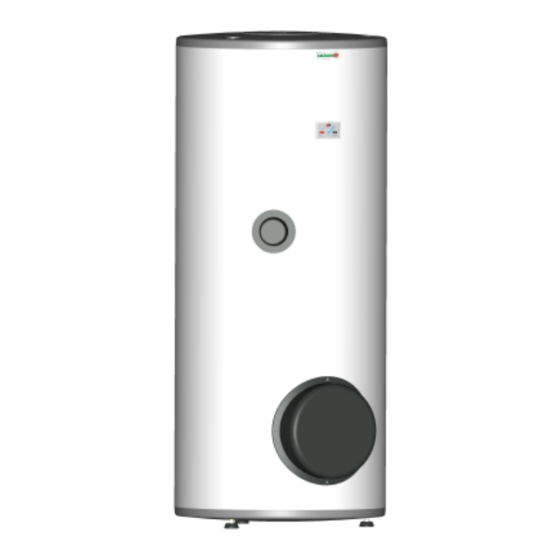
Drazice OKC 200 NTRR / BP Panduan Pengoperasian dan Instalasi

EMERGENCY POWER CONSUMPTION

If no heated water is taken from the tank, a small amount of heat leaks. This loss is
measured for a period of 24 hours at the temperature of 65°C in the heater, and at 20°C in
its ambient area. The resulting value is expressed in units [kWh/24h] and indicates the
amount of power needed to maintain the set temperature.
TANK
NOMINAL CAPACITY
HEATER
TYPES
OKC 80
OKC 100;
OKC 100/1
2
m
OKC 125;
OKC 125/1
2
m
OKC 160;
OKC 160/1
2
m
OKC 180;
OKC 180/1
2
m
OKC 200;
OKC 200/1
2
m
Table 1

1.3 DESIGN AND GENERAL HEATER DIMENSIONS

The heater tank is made of a steel plate and tested by 0.9 MPa overpressure. The inside of the tank is
enamelled. A flange is welded onto the bottom of the tank with a flange lid screwed to it.
A sealing ring is inserted between the flange lid and the flange. Thermowells for placing a heating element
and sensors of regulation thermostat and safety fuse are located in the flange lid. An anode rod is mounted
onto the M8 nut. The water reservoir is insulated by means of polyurethane foam. Electric wiring is placed
underneath the plastic removable cover. The temperature of water can be set using the thermostat. In
combined versions, a heat exchanger is welded in the pressure tank. The heat exchanger is only intended
for the heating circuit.
HEATING TIME FROM 10°C TO
(L)
75
95
120
147
175
195
60°C (hours)
2,2
2,8
3,5
4,3
4,6
5,2
ELECTRICITY
CONSUMPTION FOR
HEATING OF VOLUME
FROM 15℃ TO 65℃ V
kWh)
4,8
6
8
9,6
10,6
12
- 5 -