CommScope 3X-C70B-3XR Petunjuk Instalasi - Halaman 2
Jelajahi secara online atau unduh pdf Petunjuk Instalasi untuk Antena CommScope 3X-C70B-3XR. CommScope 3X-C70B-3XR 4 halaman.

3X-V65A-3XR Antenna
(Continued from page 1)
2.
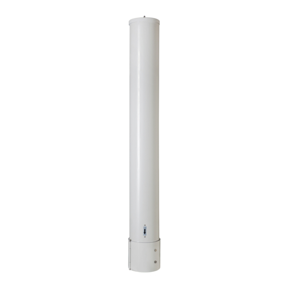
Refer to Figures 3, 4 and 5 for mounting and boresite
alignment. It is recommended that the mounting holes
be marked and made ready in the mounting surface
prior to installing the antenna.
The boresite of each antenna is shown by the boresite
indicator (featured in Figure 5). The direction of each
antenna must be considered prior to mounting to ensure
desired performance.
Equi-Spaced in 3 Positions on 228.6 mm PCD
3X R76.20
3X 120.0°
3X
17.5
Mounting Holes
Recommended hardware is M16 or 5/8"
3X 40.20
Figure 3. Mounting and Cable Routing Holes on Base.
Viewed From Bottom Side Of Antenna
Bulletin 628043 • Revision A • March 2015 Page 2 of 4
3.
Using customer supplied hardware, mount the base plate
of the antenna to the mounting surface. Tighten hardware
to securely anchor the antenna.
8 mm THICK
BASE PLATE
3X 106.07
CommScope
228.60
6X R23.21
75.00
283.50
(continued on page 3)
