ATI Technologies DDA112-BNC Panduan Pengoperasian dan Pemeliharaan - Halaman 4
Jelajahi secara online atau unduh pdf Panduan Pengoperasian dan Pemeliharaan untuk Penguat ATI Technologies DDA112-BNC. ATI Technologies DDA112-BNC 8 halaman. Aes/ebu digital audio distribution amplifiers

DISPLAYS
(Note that DSA Series units do not re-clock and provide no front panel status
information. The following section applies to DDA Series units only.)
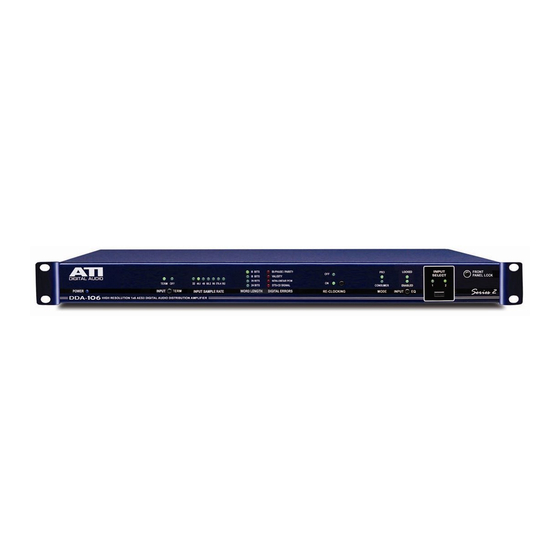
The two most significant digits of the sample rate are decoded by U1 AND U4
and displayed if the sample rate is within +/- 4% of a standard rate. Since only
two digits are displayed, readouts of 32, 44, 48, 88 and 96 correspond to actual
sampling rates within four percent of 32.0, 44.1, 48.0, 88.2 and 96kHz. The
displays are blanked if the detected frequency is out of range.
Data and transmission errors are displayed in priority order of no lock, BI-PHASE
Coding errors, PARITY errors and CRC errors. The no-lock signal is inverted and
lights when the clock recovery PLL is in LOCK. The VALIDITY indicator shows
that the previous received sample was valid when transmitted from the source
device. NO ERROR is the absence of any of the other errors and is good. The
SET indicator, used to tune the equalizer adjustment, lights when the received
data eye opening is greater than half a bit period and the recovered clock is
within range.
TRANSMITTERS
The Frame sync (FSYNC), Serial Clock (SCK), Serial audio data (SDATA),
Channel status (C), User channel data (U), and data Validity information (VERF)
are passed directly to the transmitters U9 (U18) for reformatting into the
AES/EBU output data stream TXPA (TXPB). The transmitters are Crystal
Semiconductor CS8404A devices capable of operation from 27 to 96kHz
equivalent sample rates. The transmitters operate in a transparent mode, which
allows the transmitter block structure (Channel Status, User and Validity bits) to
be slaved to the block structure of the receiver. In the transparent mode the
propagation delay of data through the CS8404A is set so that the total
propagation delay from the receiver inputs to the transmitter outputs is exactly
three sample intervals, which is less than 100 microseconds even at the lowest
sample rate.
Audio Technologies Inc.
• Tel: 856-626-3480
•
Fax: 856-504-0220
•
www.
audio.com
