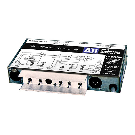
ATI Technologies M100 Panduan Pengoperasian dan Pemeliharaan - Halaman 5
Jelajahi secara online atau unduh pdf Panduan Pengoperasian dan Pemeliharaan untuk Penguat ATI Technologies M100. ATI Technologies M100 9 halaman. Ati ultimike m100 microphone amplifier operating and maintenance manual
Juga untuk ATI Technologies M100: Panduan Pengoperasian dan Pemeliharaan (8 halaman)

NOTE
Output transformers blocking RF and interrupting ground loops MUST be properly
loaded in order to provide flat response and minimum overshoot. Always be sure that the
output sees a 600 ohm load across pins 2 and 3. An occasional double load (300 ohms) is
better than no load.
REMOTE GAIN TRIM CONTROL
A 10 Kohm linear potentiometer can be connected across a single conductor shielded
cable with a standard RCA type phono plug at the M100 end. Connect the arm and one
end of the pot together and to the shield, connect the other end of the pot to the center
conductor. Decreasing resistance will cause decreasing gain to a limit of approximately -
15 dB change. If you use a pot of lower value than 10 K, you will be unable to achieve
full gain at maximum resistance. The maximum length you can run the remote gain
control cable is somewhere between three feet and mile.
MAINTENANCE
There is no routine maintenance required by your ULTIMIKE amplifier. If you have a
problem while using the M100, eliminate by substituting the microphone, cables,
connectors, load, and AC power and switch positions as possible causes before attacking
the M100.
DISASSEMBLY
1. Remove AC power.
2. Remove nine Philips head screws.
3. Pull off switch protector bracket.
4. Unlock both XLR connector PC board mounted center inserts from their cover
mounted outer shells using an .090 wide screwdriver placed into an access hole
located above the three terminals in each insert. Give each 1/8 turn CCW to
unlock; slot is horizontal when locked. DO NOT FORCE.
5. With your thumbs on the connector inserts and your fingertips on the sides of the
cover, gently slide the cover forward until the connector shells clear the inserts.
Lift the cover clear and pull the line cord grommet clear of the cover.
6. Reassembly is the reverse of the above. Don't forget the grommet.
ADJUSTMENTS
Avoid the temptation to diddle the internal trimpots R27 and R40 just to see what affects
they cause. Both are sharp null type settings, which are greatly degraded by even slight
misadjustment. Replacement of any semiconductor in the unit should not require pot
Audio Technologies Inc. | 154 Cooper Road #902 | West Berlin, NJ 08091 | Voice 856-719-9900 | Fax 856-719-9903 | www.
audio.com
