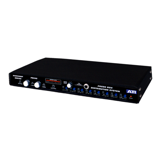
ATI Technologies PB2X8 Panduan Pengoperasian dan Pemeliharaan - Halaman 4
Jelajahi secara online atau unduh pdf Panduan Pengoperasian dan Pemeliharaan untuk Penguat ATI Technologies PB2X8. ATI Technologies PB2X8 5 halaman.

The meter circuit, A16, drives the ten-segment bargraph display with a very close
approximation of VU ballistics. The OVU LEVEL switch, S14, sets the meter OVU
point to +4, +8 or +18dBm equivalent output. The meter CAL trimpot is R176.
Headphone amplifier A17 drives both sides of a stereo headset with an in-phase
signal from the mono input or output channel selected by the rotary meter select
switch. Internal trimpot R186 sets the headphone level. If necessary, readjust
R186 for a comfortable listening level at OVU. Use stereo headphones only;
mono phones short one output.
A5C and A5D form a 40kHz oscillator and voltage doubler to generate the
+48VDC microphone phantom power. Phantom power is applied to both HI and
LO input lines thru matched 6810-ohm resistors only when the input channel is
set for microphone operation and only if the rear panel phantom power switch
(S2) is ON. Regulated + and –15VDC power is provided by IC regulators A18
and A19. A separate +10VDC unregulated supply drives the LED bargraph meter
display. PC board jumpers W1 and W2 set the nominal AC input voltage to
117Vrms. Removing W1 and W2 and inserting W3 sets the input for 234VAC. A
1/2A fuse is required for 117V operation and a 1/4A fuse for 234V.
INSTALLATION
Open the Press Box and adjust output jumper plugs before mounting the unit
under other equipment in your system.
The 1/4" and 3.5mm TRS output jacks are shipped set for -10 dBu (.25V) output
level. If you would like to dedicate some or all of them to -50dBu (2.5mV)
microphone levels, remove the top cover (4 #6 side screws, 2 #4 top screws) and
move the selected jumper plugs (Pl-M). Mark the rear label!
Plug a stereo headphone into the front panel jack and run the test tone oscillator
to check headphone loudness. Adjust PHONES trimpot R186 if necessary.
The PB2X8 Press Box may be desk mounted on its suction cup mounting feet or
EIA rack mounted in 1.75inches using optional heavy-duty rack mounting
brackets P/N 21181-501. Remove the four #6 screws from each side to attach
the optional rack mount brackets.
If you are looping inputs thru to another PB2X8 place the rear panel loop shields
switch in the LIFT position on the sending unit only. This will prevent ground loop
hum via the AC line green wire ground. If you use a TRS loop in jack as your
main (or loop) input, be sure the shield switch is in the GND position. The XLR
input jack's pin 1 (shield) is permanently grounded.
The wiring convention used on the PB2X8 XLR connectors is pin 2 HI, pin 3 LO,
pin 1 shield. TRS connectors, Tip HI, Ring LO, Sleeve is shield.
Audio Technologies Inc.
856-719-9900
www.
audio.com
