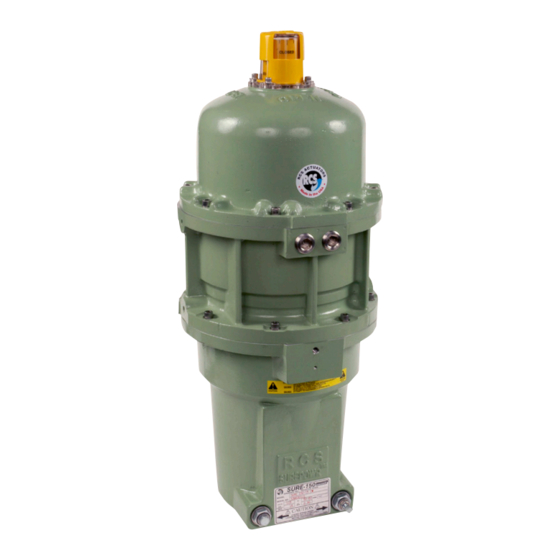
Dresser Surepowr Sure 150 Panduan Instalasi - Halaman 3
Jelajahi secara online atau unduh pdf Panduan Instalasi untuk Pengontrol Dresser Surepowr Sure 150. Dresser Surepowr Sure 150 16 halaman. Rcs actuators

1. Actuator Marking
ATEX Explosion
Proof Enclosure
"d"/Dust
Protection by
Enclosure "Tb"
Name and
Dresser NGS
Address of
16240 Port
Manufacturer
Northwest Drive
Houston, TX
77041
Actuator Type
Electrical
Mechanical
Surepowr Series
Certificate
SIRA 15 ATEX
Number
1058x/IECEx SIR
15,0034X
εx II 2 GD;
Specific Marking
-NN°C > Ta >
No. of notified
Sira 15 ATEX
audit body
1058x
Gas Marking
Ex d IIB T5 Gb
Dust Marking
Ex tb IIIC T85°C
DbAmbient
Temperature
Ambient
-20°C (-4°F) to
Temperature
+65°C (150°F)
Note
Any temperature
below -20°C
(-4°F) (over
pressure
test required)
CE Marking
Machinery
Directive;
2004/42/EC
(EN 12100:2010,
EN 14121-1:2007)
CE Marking
EMC Directive;
2004/108/EC
(EN 61000-6-
4:2007,
EN 61000-6-
2:2005)
NOTICE:
The Actuator Marking Plate shall not be damaged,
covered up or painted over.
Actuator identification and specifications must remain visible.
North American
Class/Div.
Europe CE
marking
Dresser NGS
16240 Port
Northwest Drive
Houston, TX
77041
Electrical
Mechanical
Surepowr Series
Master Contract:
157578
65°C
CSA
Class I, Div I,
Grp. C,D
Class II, Div I
Grp E, F, G
-40°C (-40°F) to
+65°C (150°F)
NA
NA
2. Special Conditions for Safe Use
(ATEX)/Conditions of Certification
(IECEx)
1.
The equipment uses M10x1.5 stainless steel special
fasteners of grade A4-80 and yield strength 600 MPa. If
fasteners are replaced, they shall be replaced with the
equivalent size and grade.
2.
Some external parts of the equipment are non-
conducting and may generate an ignition-capable
level of electrostatic charge under certain extreme
conditions. Ensure that the equipment is not installed
in a location where it may be subjected to external
conditions (such as high-pressure steam) that might
cause build-up of electrostatic charges on non-
conducting surfaces. Additionally, the equipment
should be cleaned with a damp cloth.
3.
The equipment contains flamepaths that are other
than the relevant minimum or maximum dimensions
as specified in IEC 60079-1:2012 Table 1. The essential
parameters are:
Flamepath
Type
Cover to
Cylindrical
Shaft
Cover to
Flange
Gear Case
Gear Case
Flange
to Spring
Housing
Shaft to
Spigot
Yoke
Yoke to
Rabbet
Spring
Housing
3. Ratings
Power [kW]
Nominal Supply Voltage
[V]
Nominal Current [A]
Nominal Torque [Nm]
Duty Cycle (max
frequency)
Temperature
Protection Class
Weight
The actuator has been tested and certified for Ingress
Protection IP 66/67 and type 4, 4X & 6.
Min.
Max.
design
design
length
gap
25.89 mm
0.10 mm
23.39 mm
.0762 mm
23.37 mm
.0762 mm
19.40 mm
.08 mm
26.14 mm
.0762 mm
(flange)
.1mm
(cylinder)
Sure 150
115/120;
220/230 (VAC)
(50/60 Hz)
1.9
136
25
See Above
d
120 lb (55kg)
3
