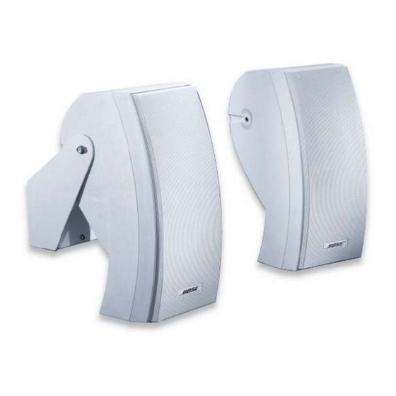
Bose 302 A Panduan Servis - Halaman 4
Jelajahi secara online atau unduh pdf Panduan Servis untuk Pembicara Bose 302 A. Bose 302 A 10 halaman. Loudspeaker (commercial indoor/outdoor 70v/100v distributed applications)
Juga untuk Bose 302 A: Panduan Pemasang (13 halaman), Lembar Data Teknis (2 halaman), Panduan Pemasang (7 halaman)

DISASSEMBLY/ASSEMBLY PROCEDURES
1. Grille and Baffle Removal
1.1 Grasp the edge of the grill (10) and pull it
off.
1.2 Remove the six screws (17) that secure
the baffle to the cabinet and then pull off the
baffle.
2. Grille and Baffle Replacement
2.1 To prevent air leaks, apply a new woofer
mount gasket (13). To prevent wire buzzes,
insert the wires into the cabinet's wire chan-
nel. Line up the baffle so that the baffle's
woofer mount fits into the groove in the
cabinet. Replace the six screws (17) that
secure the baffle to the cabinet.
2.2 Align the grille (10) with the cabinet so
that the logo (14) is over the Twiddler
drivers (2). Press the grille into place.
3. Twiddler Removal.
3.1 Perform procedure 1.1 and then remove
the four screws (16) that secure the Twiddler
driver (2) to the cabinet.
3.2 Lift out the Twiddler driver, make a note of
the wiring configuration and cut the wires as
close as possible to the wire terminal.
4. Twiddler Replacement
4.1 Referring to the note taken in 3.2, attach
the wires to the Twiddler driver (2).
4.2 Line up the Twiddler driver in the cabinet
and replace the four screws (16) that secure it
in place.
5. Woofer Removal
5.1 Perform procedure 1.
5.2 Make a note of the wiring configuration
and then cut the wires as close as possible to
the woofer's (1) wire terminal.
(Refer to Figure 4)
5.3 Remove the four screws (16) that secure
the woofer to the baffle. Lift out the woofer.
6. Woofer Replacement
6.1 To prevent air leaks, use a new woofer
gasket (15) and woofer mount gasket (13).
Line up the woofer (1) in the baffle so that the
wire terminal is facing toward the Twiddler
drivers (2). Replace the four screws (16) that
secure the woofer to the baffle.
6.2 Referring to the note taken in procedure
5.2, attach the wires to the woofer.
6.3 Place the foam tape woofer mount gasket
(13) around the edge of the woofer mount
where it contacts the cabinet.
7. RLC Circuit Component Removal
TM
7.1 Perform procedure 1.
7.2 Remove the capacitor (5), resistor (6) or
inductor (4) by cutting its leads. Remove the
screw (16) that secures the inductor to the
cabinet and cut the inductor's leads.
8. RLC Circuit Component Replacement
8.1 Replace the capacitor (5), resistor (6) or
inductor (4) by soldering its leads to the lug
from which it was removed. Replace the
screw (16) that secures the inductor to the
cabinet. Refer to Figures 1 and 3.
9. Crossover Capacitor Removal
9.1 Perform procedure 1.
9.2 Remove the four screws (16) that secure
the Twiddler driver panel (11) to the baffle.
Pry off the panel.
9.3 Cut the wires as close as possible to the
terminals of the capacitor (3).
4
