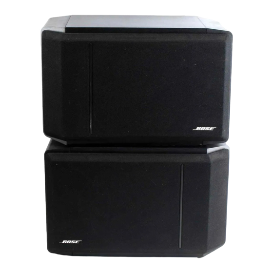
Bose 301 Series Panduan Servis - Halaman 6
Jelajahi secara online atau unduh pdf Panduan Servis untuk Sistem Pembicara Bose 301 Series. Bose 301 Series 12 halaman.

Note: Before performing any tests, remove both
grilles by following the grille removal instructions in
the disassembly section of this manual.
1. Woofer Rub and Tick Test: Connect the
output of a signal generator to the input of a
power amplifier. Connect the output of the
power amplifier to the input terminals of the
speaker under test, (see Figure 1). Adjust the
frequency of the generator to 45 Hz and the
amplifier output to 8 Vrms. No extraneous
noises such as rubbing, scraping or ticking
should be heard.
Note: To distinguish between normal suspen-
sion noise and rubs or ticks, slightly displace
the cone of the woofer with your fingers. If the
noise can be made to go away or get worse, it
is a rub or tick and the woofer should be re-
placed. If the noise stays the same, it is normal
suspension noise and the woofer is fine. Sus-
pension noises will not be heard with program
material.
2. Woofer Sweep Test: Sweep the signal genera-
tor from 10 Hz to 5 kHz using the 8 Vrms signal.
There should be no loud extraneous sounds. If
there are any loud buzzes or distortion, replace
the woofer.
Back of Speaker
Under Test
TEST PROCEDURES
Test Connections, 301
Audio Signal
Generator
+ -
Black ( - )
Note: There should not be any buzzes or
rattles from within the speaker cabinet. Re-
dress any wire or component that buzzes.
3. Tweeter Sweep Test: Reduce the amplifier
output to 3 Vrms and continue sweeping from 5
kHz to 15 kHz. Replace either of the tweeters
in which buzzing or distortion occurs.
4. Air Leak Test: Using an 8 Vrms signal, set the
generator frequency to 45 Hz. Listen for air
leaks around the woofer, tweeters and cabinet
seams (glue joints). Any air leaks will be heard
as a sputtering or hissing sound. The repair of
air leaks can be made by repositioning the
transducer gaskets.
5. Woofer Phase Test:
Note: In this test, supply voltage should only
be momentarily applied to the speaker input
terminals to avoid possible damage to the
speaker.
Set a DC power supply to 8 volts. To ensure
that the woofer is connected in phase, connect
the positive lead of the supply to the positive (+)
speaker input terminal and the negative lead to
the negative (-) input terminal. The woofer
should move outwards with the application of
the supply voltage.
®
Series IV Speaker
Power Amplifier
Input
Output
-
-
+
+
RIGHT
Red ( + )
5
FIGURE 1
