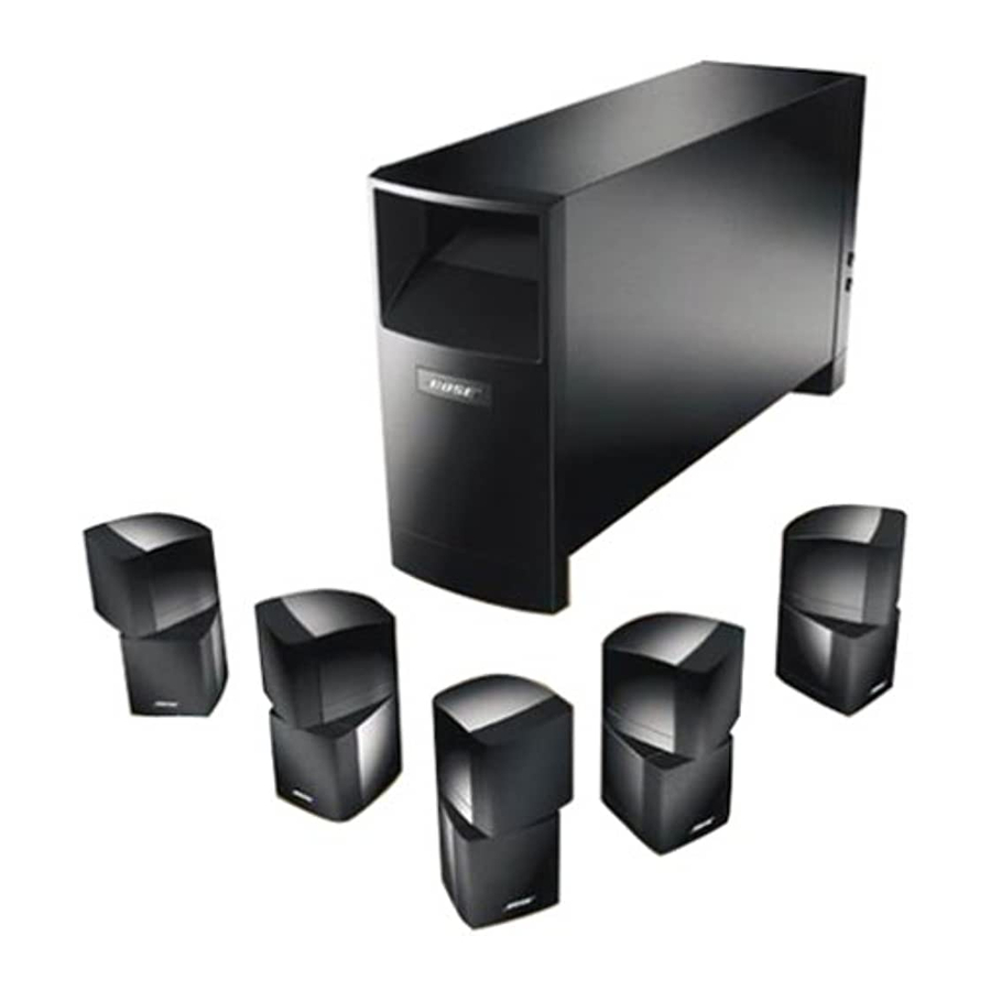
Bose Acoustimass 15 Panduan Pemilik - Halaman 10
Jelajahi secara online atau unduh pdf Panduan Pemilik untuk Sistem Teater Rumah Bose Acoustimass 15. Bose Acoustimass 15 18 halaman. Bose owner's manual home entertainment speaker systems acoustimass 15 series ii, acoustimass 16
Juga untuk Bose Acoustimass 15: Panduan Pemilik (18 halaman), Panduan Pemilik (16 halaman)

Setting Up
8
Connect the Powered Acoustimass
cube arrays
The 50 foot (15 m) cable with two pairs of wires connects the Powered Acoustimass module
to the Right and Left surround cube arrays. Each has an individual plug on the module end.
1. The wire marked R connects the module to the right surround speaker (on your right as
you face the TV). As shown in Figure 5, press the terminal tab on the back of cube array to
insert the marked wire into the red terminal and the plain wire into the black terminal.
2. The wire marked L connects the module to the left surround speaker.
3. Insert the connectors firmly into their jacks at the Powered Acoustimass module.
Connect the Powered Acoustimass module to the receiver
The 20 foot (6m) cable with five pairs of wires and a single wire with an RCA plug connects
the module to the outputs on the receiver as shown in the table below.
Note: The RCA plug comes with a cover installed. Remove this cover for connection to the
LFE/SUBWOOFER OUT jack. If your receiver has no LFE/SUBWOOFER OUT jack, leave the
plug cover in place; in this case this wire will not be used.
• Match the polarity on the receiver. Connect the wire pairs in phase (+ to + and – to –).
a. Attach each marked wire (+) to the appropriate + terminal.
b. Attach each plain wire (–) to the appropriate – terminal.
• Connect the RCA plug to the receiver's LFE/SUBWOOFER OUT jack.
• At the Powered Acoustimass module, be sure the receiver cable connector is firmly
inserted.
WIRE
CENTER
RIGHT
LEFT
RIGHT SURROUND
LEFT SURROUND
LFE RCA PLUG
CAUTION: Do not connect the Powered Acoustimass module directly to your television
unless the television provides surround decoding circuitry and amplified outputs for all
channels.
CAUTION: Do not allow exposed wires to brush against each other; this could damage
your receiver.
October 22, 2001
®
module to the surround
RECEIVER CONNECTION
(
,
)
CENTER
MAIN
A
(
,
)
RIGHT FRONT
MAIN
A
(
,
)
LEFT FRONT
MAIN
A
(
)
RIGHT SURROUND
REAR
(
)
LEFT SURROUND
REAR
LFE SUBWOOFER OUT
AM194452_06_V.pdf
