Bose Companion 3 Series II Panduan Servis - Halaman 31

Jelajahi secara online atau unduh pdf Panduan Servis untuk Sistem stereo Bose Companion 3 Series II. Bose Companion 3 Series II 36 halaman. Multimedia speaker system
Juga untuk Bose Companion 3 Series II: Panduan Pemilik (40 halaman), Panduan Pemilik (40 halaman), Panduan Pemilik (22 halaman), Panduan Pemilik (10 halaman), Panduan Pemilik (20 halaman), Panduan Pemilik (26 halaman), Panduan Pengaturan Cepat (2 halaman), Panduan Pengaturan Cepat (2 halaman), Petunjuk Perakitan Rinci (2 halaman), Panduan Instalasi (20 halaman), Spesifikasi (6 halaman), Brosur & Spesifikasi (4 halaman), Panduan Pemilik (19 halaman), Panduan Servis (16 halaman)
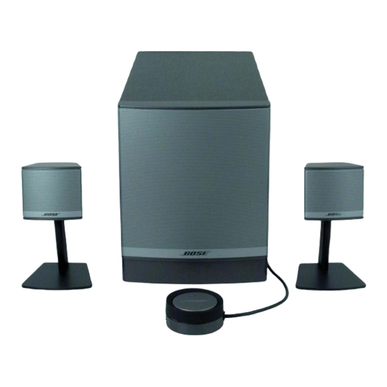
Bose Companion 3 Series II Panduan Servis
Companion® 3 Series II Multimedia Speaker System
Refer to the Companion® 3 Multimedia Speaker System service manuals, part number 297700
for schematics, PCB layouts and parts lists.
Preventative Repair Measures
Note: Perform the following on all units returned for repair.
Product
Check
Units built before 10/23/2007
(DOM 7289).
Companion 3
series II
Product
Symptom
Intermittent power
Companion 3
series II
Intermittent power
Companion 3
series II
No Audio
Companion 3
series II
Troubleshooting Tips
Action
Units built before 10/23/2007 will have the Aishi
capacitor C7 installed on the power supply PCB.
Replace C7 with a United Chemi-Con (UCC)
capacitor. Refer to the service manual for the part
number. The DOM cut-in date only applies to U.S.
variants. Refer to Service Bulletin: 271885-B4 for
further information.
Troubleshooting Tips
Check
Either J308 or the
control pod itself can be
defective
Check J1
Check U301
1
Action
Use a test control pod to identify if
the problem is with the customer's
control pod or the connector J308.
If the test control pod works, the
problem can be identified as the
customer having a defective control
pod. If the control pod does not fix
the problem, J308 is the failed
component. J308 is not repairable.
The module assembly would have
to be replaced. Refer to the Service
Manual for the module assembly
part number.
Sometimes J1 is not seated
properly and may become
intermittent. If J1 is intermittent, the
cable may need to be replaced or
reseated.
Check pins 6 and 20 for 15Vdc. If
the 15Vdc is not present, check all
other power supply voltages. If the
power supply voltages are present,
inject a 1KHz signal into J302.
Check pins 14 (right in) and 15 (left
in) and then pins 17 (right out) and
21 (left out). If audio is coming in
and nothing is going out, replace
U301