Bose Personalized Amplification System Panduan Pemecahan Masalah - Halaman 11
Jelajahi secara online atau unduh pdf Panduan Pemecahan Masalah untuk Sistem stereo Bose Personalized Amplification System. Bose Personalized Amplification System 50 halaman.
Juga untuk Bose Personalized Amplification System: Panduan Pemilik (28 halaman)

DSP
The DSP, U461 [DSP PCB sheet 3, B4] is an Analog Devices 21065L general purpose floating
point digital signal processor. There are two of these DSP ICs used in the system. Each is
capable of about 40MIPs of performance. The DSPs are mainly used to process sound effects.
They provide:
•
Two channels noise gate
•
Two channels tone control
•
Two channels clip calculate
•
Two channels parameter equalizer
•
Four channels mixer
•
Two channels system equalizer
•
Two channels limiter
The DSPs have no internal ROM, at boot time they load themselves from the external FLASH
U462 [C7]. This boot process is more or less automatic, no intervention from the microcontroller
is required.
The signal required to connect the DSPs to the boot FLASH include:
•
An external data address bus (24 bits, of which 18 are used)
•
An external data bus (32 bits, of which 8 are used)
•
Bus control signals
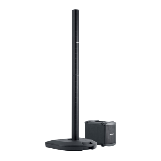
Finally the signals are brought out through a D/A stereo converter. The "left" channel contains
the signal for the L1, the "right" channel the signal for the bass module. The L1 signal is routed
to power amps 1 and 2, the B1 signal to power amp 3. The B1 signal is also available as a
balanced signal at the "Bass Line Out" TRS connector.
Each power amp has an external input that replaces the signal from the D/A converter when a
plug is inserted. In addition there is an "All Amps In" input that replaces the input signal to all 3
power amps when inserted. Individual inputs take precedence over the "All Amps Input". Each
power amp output is available through a Neutrik
nally the outputs of power amp 1 and 2 are routed to a Molex connector in the base of the
power stand which connects to the L1s when inserted. Power Amp 1 gets routed to the upper L1
and power amp 2 to the lower L1.
THEORY OF OPERATION
11
®
®
Speakon
connector at pins 1+ and 1-. Inter-
