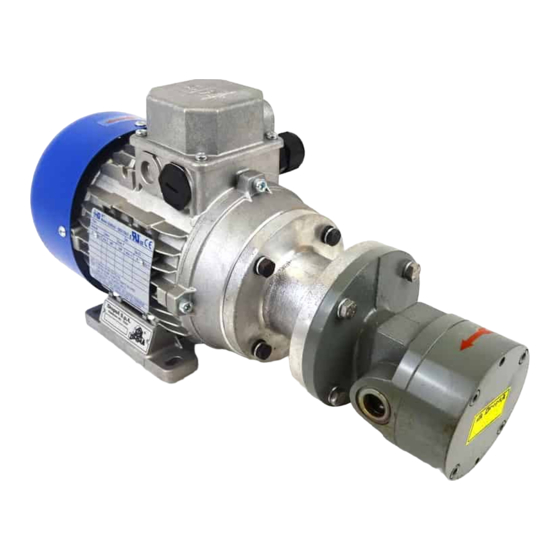
DROPSA 37007 Panduan Pengguna dan Pemeliharaan - Halaman 10
Jelajahi secara online atau unduh pdf Panduan Pengguna dan Pemeliharaan untuk Pompa Air DROPSA 37007. DROPSA 37007 16 halaman. Motor driven gear pumps

Gear pump and electro-gear pumps (pumps with flange)
Max Pressure = 30 bar for continuous working – Max Pressure =60 bar for intermittent working.
Fluid working temperature = 20÷100 ºC with low and medium oil viscosity.
Note: For pumps either with clockwise rotation or bi-rotational with suction on left side, connect suction line to threaded port 1
and delivery line to threaded port 2 ;
For pumps either with counter - clockwise rotation or bi-rotational with suction on right side connect suction line to threaded
port 2 and delivery line to threaded port 1;
WITHOUT BY PASS
Rotation#
Liters
Left
Right
2
37066 37054
3,5
37001
5,5
37068 37056
10
37018 37004
19
37007
26
37058
32
37123 37010
*45
37013
WITH BY PASS
Rotation#
Liters
Left
Right
2
37055
3,5
37002
5,5
37057
10
37016 37005
19
37082 37008
26
37059
32
37011
*45
37014
REVERSIBLE
Sunction
Liters
Left
Right
2
37067
3,5
37020 37003
5,5
37069
10
37006
19
37009
26
37083
32
37012
* Please ask to nearest Dropsa for availability
Dimensions and features may change without notice
Weight
Gas
kg
D
E
F
G
0,9
1/4
70
50
60
1,9
3/8 100
70
84
3,2
1/2 120
90
100
5
3/4 140 100 120
8
1
150 110 130 11,5 11 18
Peso
Gas
kg
D
E
F
G
H
1
1/4
70
50
60
5,7
2,1
3/8 100
70
84
7
3,5
1/2 120
90
100
7
5,5
3/4 140 100 120
9
8,2
1
150 110 130 11,5 11 18
Weight
Gas
kg
D
E
F
G
0,9
1/4
70
50
60
5,7 6,5 10
1,9
3/8 100
70
84
3,2
1/2 120
90
100
5
3/4 140 100 120
Dimensions (mm)
H
J
K
L
M
N
5,7
6,5 10
2
3
11,2
7
8,5 12
3
4
13,5 42,5
7
9
14 3,5
5
16
53,5
9
10 16
4
5
18
4
6
20,5 65,5 138,5 22,5 140 130 38 ... ... ...
Dimensions (mm)
J
K
L
M
N
O
6,5 10
2
3
11,2
32
8,5 12
3
4
13,5 42,5 ... 12,3
9
14 3,5
5
16
53,5 ... 15,2
10 16
4
5
18
59
4
6
20,5 65,5 ... 22,5 140 130 38 138,5
Dimensions (mm)
H
J
K
L
M
N
O
2
3
11,2
32
7
8,5 12
3
4
13,5 42,5 ... 12,3
7
9
14 3,5
5
16
53,5 ... 15,2
9
10 16
4
5
18
59
O
P
Q
R
S
T
32
63
8,7
60
60
15 ... ... ...
85
12,3
80
80
19 ... ... ...
102
15,2
98
90
26 ... ... ...
59
113
18,9 116 108 34 ... ... ...
# Looking at the pump from shaft side
P
Q
R
S
T
U
...
8,7
60
60
15
63
80
80
19
85
98
90
26
104
... 18,9 116 108 34
117
# Looking at the pump from shaft side
P
Q
R
S
T
U
...
8,7
60
60
15
63
80
80
19
87,5
98
90
26 108,5 ... 113,5
... 18,9 116 108 34 120,5 ...
U V
Z
V
Z
58
...
78
...
86
...
102,5 ...
113
...
V
Z
...
67,5
...
92
125
10
