BECKWITH ELECTRIC Syncrocloser M-3410A Manual - Halaman 10
Jelajahi secara online atau unduh pdf Manual untuk Sistem Kontrol BECKWITH ELECTRIC Syncrocloser M-3410A. BECKWITH ELECTRIC Syncrocloser M-3410A 18 halaman.
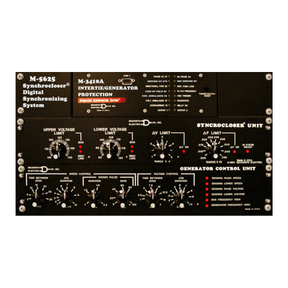
M‑5625 Digital Synchronizing System
Metering
The Digital Synchronizing System provides metering of voltages, currents, real power, reactive power,
power factor, frequency and positive sequence impedance.
Metering Accuracies are:
Voltage:
0.5 V or 0.5%, whichever is greater (Range 0 to 600 V)
Current:
5 A rating, 0.1 A or 3%, whichever is greater (Range 0 to 14 A)
1 A rating, 0.02 A or 3%, whichever is greater (Range 0 to 2.8 A)
Power:
0.02 PU or 2%, whichever is greater
Frequency:
0.03 Hz (from 57 to 63 Hz for 60 Hz models; from 47 to 53 Hz for 50 Hz models)
Sync Scope:
The Sync Scope screen displays a phasor representation, the phase angle, delta voltage
and delta frequency of generator and incoming voltages. The display should not be used to
determine in phase conditions for manual synchronizing because of communications time
delay.
Oscillographic Recorder
The oscillographic recorder provides comprehensive data recording of all monitored waveforms, input
contacts and output contacts, storing up to 120 cycles of data. The total record length is configured for
one or two partitions. A programmable post trigger delay (5 to 95%) is incorporated to capture breaker
operation. The oscillograph is triggered either remotely using the serial interface, or designated status input
signals or M-5625 programmable output operations. Storage of oscillographic records is nonvolatile, and will
be retained even without power, as long as the on-board battery is healthy.
Oscillographic data can be downloaded using serial communication in Common Format For Transient Data
Exchange (COMTRADE) format as specified by IEEE Standard C37.111-1999.
Sequence of Events
A total of 32 nonvolatile events can be stored. The recorded information includes the function(s) operated,
the function(s) picked up, input/output contact status and time stamp. The events can be retrieved through
the communications port. After the 32nd event is stored, additional events result in the oldest event being
dropped (FIFO). The information is time-stamped to 1 ms resolution.
Calculations
Current and Voltage Values: Uses discrete Fourier transform (DFT) algorithm on sampled (32 times per
cycle) voltage and current signals to extract fundamental frequency phasors for calculations. When set for
RMS measurement, uses a time domain algorithm to calculate the voltage magnitude.
Power Input
Nominal 120 V ac, 50/60 Hz, 100 to a maximum of 140 V ac, 22 VA maximum burden at 120 V ac.
Other power input options are available for M-3410A only:
Nominal
12/24 V dc
48 V dc
120 V ac/125 V dc
Range
9 to 36 V dc
36 to 75 V dc
85 to 150 V ac/V dc
–10–
Burden
<5 VA
<5 VA
<5 VA