Daikin R32 Split Series Panduan Instalasi - Halaman 9

Jelajahi secara online atau unduh pdf Panduan Instalasi untuk Kipas angin Daikin R32 Split Series. Daikin R32 Split Series 16 halaman. R32 split series
Juga untuk Daikin R32 Split Series: Panduan Instalasi (17 halaman), Panduan Instalasi (16 halaman), Panduan Instalasi (16 halaman), Panduan Instalasi (16 halaman), Panduan Instalasi (17 halaman), Panduan Instalasi (16 halaman), Panduan Instalasi (20 halaman), Panduan Instalasi (14 halaman), Panduan Instalasi (14 halaman), Panduan Pengoperasian (16 halaman), Panduan Pengoperasian (16 halaman), Panduan Pengoperasian (8 halaman), Panduan Instalasi (17 halaman), Panduan Instalasi (20 halaman), Panduan Instalasi (20 halaman), Panduan Instalasi (16 halaman), Panduan Instalasi (16 halaman), Panduan Instalasi (14 halaman), Panduan Instalasi (14 halaman), Panduan Instalasi (16 halaman), Panduan Instalasi (17 halaman), Panduan Instalasi (20 halaman), Panduan Instalasi (13 halaman)
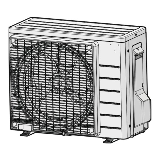
Daikin R32 Split Series Panduan Instalasi
▪ Flare connections: Only use annealed material.
▪ Piping temper grade and thickness:
Outer diameter
Temper grade
(Ø)
6.4 mm (1/4")
Annealed (O)
12.7 mm (1/2")
(a)
Depending on the applicable legislation and the maximum
working pressure of the unit (see "PS High" on the unit name
plate), larger piping thickness might be required.
5.1.2

Refrigerant piping insulation

▪ Use polyethylene foam as insulation material:
▪ with a heat transfer rate between 0.041 and 0.052 W/mK (0.035
and 0.045 kcal/mh°C)
▪ with a heat resistance of at least 120°C
▪ Insulation thickness
Pipe outer diameter
Insulation inner
)
diameter (Ø
p
6.4 mm (1/4")
8~10 mm
12.7 mm (1/2")
14~16 mm
Ø
Ø
i
i
Ø
Ø
p
p
t
If the temperature is higher than 30°C and the humidity is higher
than RH 80%, the thickness of the insulation materials should be at
least 20  mm to prevent condensation on the surface of the
insulation.
5.1.3
Refrigerant piping length and height
difference
What?
Maximum allowable pipe length
Minimum allowable pipe length
Maximum allowable height distance
5.2

Connecting the refrigerant piping

DANGER: RISK OF BURNING/SCALDING
CAUTION
▪ No brazing or welding on site for units with R32
refrigerant charge during shipment.
▪ During installation of the refrigeration system, joining of
parts with at least one part charged shall be performed
taking into account the following requirements: inside
occupied spaces non-permanent joints are NOT
allowed for R32 refrigerant except for site made joints
directly connecting the indoor unit to piping. Site made
joints directly connecting piping to indoor units shall be
of non-permanent type.
5.2.1
To connect the refrigerant piping to the
outdoor unit
▪ Piping length. Keep field piping as short as possible.
▪ Piping protection. Protect the field piping against physical
damage.
RXJ42+50A
R32 split series
3P512025-12X – 2021.12
(a)
Thickness (t)
Ø
≥0.8 mm
t
Insulation thickness
)
(t)
i
≥10 mm
≥13 mm
Distance
30 m
3 m
20 m
WARNING
Connect the refrigerant piping securely before running the
compressor. If the refrigerant piping is NOT connected and
the stop valve is open when the compressor is run, air will
be sucked in. This will cause abnormal pressure in the
refrigeration cycle, which may result in equipment damage
and even injury.
NOTICE
▪ Use the flare nut fixed to the unit.
▪ To prevent gas leakage, apply refrigeration oil ONLY to
the inside of the flare. Use refrigeration oil for R32
(FW68DA).
▪ Do NOT reuse joints.
1 Connect the liquid refrigerant connection from the indoor unit to
the liquid stop valve of the outdoor unit.
a
c b
a
Liquid stop valve
b
Gas stop valve
c
Service port
2 Connect the gas refrigerant connection from the indoor unit to
the gas stop valve of the outdoor unit.
NOTICE
It is recommended that the refrigerant piping between
indoor and outdoor unit is installed in a ducting or the
refrigerant piping is wrapped with finishing tape.
5.3

Checking the refrigerant piping

5.3.1

To check for leaks

NOTICE
Do NOT exceed the unit's maximum working pressure (see
"PS High" on the unit name plate).
NOTICE
ALWAYS use a recommended bubble test solution from
your wholesaler.
NEVER use soap water:
▪ Soap water may cause cracking of components, such
as flare nuts or stop valve caps.
▪ Soap water may contain salt, which absorbs moisture
that will freeze when the piping gets cold.
▪ Soap water contains ammonia which may lead to
corrosion of flared joints (between the brass flare nut
and the copper flare).
1 Charge the system with nitrogen gas up to a gauge pressure of
at least 200  kPa (2  bar). It is recommended to pressurize to
3000 kPa (30 bar) in order to detect small leaks.
2 Check for leaks by applying the bubble test solution to all
connections.
3 Discharge all nitrogen gas.
5 Piping installation
Installation manual
9