Daikin R32 Split Series Panduan Instalasi - Halaman 11

Jelajahi secara online atau unduh pdf Panduan Instalasi untuk Kipas angin Daikin R32 Split Series. Daikin R32 Split Series 16 halaman. R32 split series
Juga untuk Daikin R32 Split Series: Panduan Instalasi (17 halaman), Panduan Instalasi (16 halaman), Panduan Instalasi (16 halaman), Panduan Instalasi (16 halaman), Panduan Instalasi (17 halaman), Panduan Instalasi (16 halaman), Panduan Instalasi (20 halaman), Panduan Instalasi (14 halaman), Panduan Instalasi (14 halaman), Panduan Pengoperasian (16 halaman), Panduan Pengoperasian (16 halaman), Panduan Pengoperasian (8 halaman), Panduan Instalasi (17 halaman), Panduan Instalasi (16 halaman), Panduan Instalasi (20 halaman), Panduan Instalasi (20 halaman), Panduan Instalasi (16 halaman), Panduan Instalasi (14 halaman), Panduan Instalasi (14 halaman), Panduan Instalasi (16 halaman), Panduan Instalasi (17 halaman), Panduan Instalasi (20 halaman), Panduan Instalasi (13 halaman)
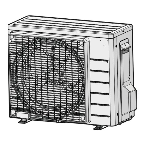
Daikin R32 Split Series Panduan Instalasi
WARNING
▪ All wiring MUST be performed by an authorised
electrician and MUST comply with the applicable
national wiring regulation.
▪ Make electrical connections to the fixed wiring.
▪ All components procured on-site and all electrical
construction
MUST
legislation.
WARNING
ALWAYS use multicore cable for power supply cables.
WARNING
Use an all-pole disconnection type breaker with at least
3  mm between the contact point gaps that provides full
disconnection under overvoltage category III.
WARNING
If the supply cord is damaged, it MUST be replaced by the
manufacturer, its service agent or similarly qualified
persons in order to avoid a hazard.
WARNING
Do NOT connect the power supply to the indoor unit. This
could result in electrical shock or fire.
WARNING
▪ Do NOT use locally purchased electrical parts inside
the product.
▪ Do NOT branch the power supply for the drain pump,
etc. from the terminal block. This could result in
electrical shock or fire.
WARNING
Keep the interconnection wiring away from copper pipes
without thermal insulation as such pipes will be very hot.
DANGER: RISK OF ELECTROCUTION
All electrical parts (including thermistors) are powered by
the power supply. Do NOT touch them with bare hands.
DANGER: RISK OF ELECTROCUTION
Disconnect the power supply for more than 10  minutes,
and measure the voltage at the terminals of main circuit
capacitors or electrical components before servicing. The
voltage MUST be less than 50 V DC before you can touch
electrical components. For the location of the terminals,
see the wiring diagram.
b
c
d
e
f
DC+
DC-
h
a
a
Multimeter (DC voltage range)
b
S80 – reversing solenoid valve lead wire
c
S70 – fan motor lead wire
d
LED
e
S90 – thermistor lead wire
f
S20 – electronic expansion valve lead wire
g
S40 – thermal overload relay lead wire
h
DB1 – diode bridge
ARXD25+35A5V1B
R32 Split series
3P650253-15Q – 2022.12
comply
with
the
applicable
g
7.1
Specifications of standard wiring
components
NOTICE
We recommend using solid (single-core) wires. If stranded
wires are used, slightly twist the strands to consolidate the
end of the conductor for either direct use in the terminal
clamp or insertion in a round crimp-style terminal. Details
are described in "Guidelines when connecting the electrical
wiring" in the installer reference guide.
Component
Power supply cable Voltage
Phase
Frequency
Wire sizes
Interconnection cable
Recommended field fuse
Earth leakage circuit breaker
7.2
To connect the electrical wiring to
the outdoor unit
1 Remove the service cover.
2 Open the wire clamp.
3 Connect the interconnection cable and power supply as follows:
a
a
Interconnection cable
b
Power supply cable
c
Circuit breaker
d
Residual current device
e
Power supply
f
Earth
4 Tighten the terminal screws securely. We recommend using a
Phillips screwdriver.
5 Install the service cover.
7 Electrical installation
220~240 V
1~
50 Hz
Must comply with
applicable legislation
Minimum cable section of
2.5 mm² and applicable
for 220~240 V
20 A
Must comply with
applicable legislation
50 Hz
220-240 V
b
c
d
e
f
Installation manual
11