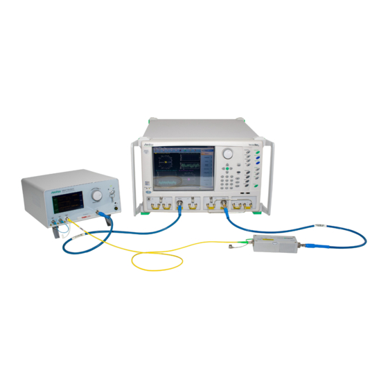
Anritsu Company VectorStar ME7848A-0171 Panduan Memulai Cepat - Halaman 9
Jelajahi secara online atau unduh pdf Panduan Memulai Cepat untuk Alat Ukur Anritsu Company VectorStar ME7848A-0171. Anritsu Company VectorStar ME7848A-0171 15 halaman. Opto-electronic network analyzer systems
Juga untuk Anritsu Company VectorStar ME7848A-0171: Panduan Memulai Cepat (17 halaman)

Figure 2.
Example Plot of |S21| for the System Check on a ME7848A-0270 System at +5 and +2 dBm Optical
Power Levels. The absolute values and approximate shape are of interest.
In
Figure
2, the blue curve is at 5 dBm optical power out of the modulator which is the test condition
mentioned above. The red curve is at +2 dBm optical power for information. ME7848A-0271 systems will have
a similar curve shape but shifted lower in values than the red curve (due to lower O/E responsivity).
ME7848A-0240 systems will roll-off faster and have a shift down in values relative to the red curve (due to
lower O/E responsivity).
Functional Test
1. Measurement setup
a. Set the VNA to sweep from 70 kHz to the 40/70 GHz (depending on the system), 201 points, 100 Hz
IFBW, +5 dBm for -0240 systems and -10 dBm for the -027x systems.
b. Set the display parameter to be user-defined b2/1|P1.
c. Connect an RF thru line (ends of RF cables connected together).
d. Perform a port 2 test receiver calibration (under the power menu). The plot after the cal should be
a flat line at -10 dB.
2. Connect the port 1 RF cable to the modulator input and the port 2 RF cable to the O/E calibration module
as before. Also ensure the optical patch cord is in place. Activate the laser and set the modulator as
discussed in the previous section.
ME7848A QSG
PN: 10410-00777 Rev. B
3. System Check
QSG-9
