ATX Q series Panduan Pemasangan & Pengoperasian - Halaman 11
Jelajahi secara online atau unduh pdf Panduan Pemasangan & Pengoperasian untuk Penguat ATX Q series. ATX Q series 18 halaman. Qpair redundancy switch amplifier system

SET-UP PROCEDURE
3.
Set-up Procedure
1.
Remove the front cover. See Appendix 1 for the proper method to remove the front cover.
2.
Connect main input cable to the RF INPUT on the left rear part of the chassis.
3.
Connect a cable from the TO AMP 1 port to RF IN of AMP 1 on the rear of the chassis.
4.
Connect a cable from the TO AMP 2 port to RF IN of AMP 2 on the rear of the chassis.
5.
Connect a cable from the FROM AMP 1 port to RF OUT of AMP 1 on the rear of the chassis.
6.
Connect a cable from the FROM AMP 2 port to RF OUT of AMP 2 on the rear of the chassis.
7.
Connect your main output cable to the RF OUT port on the rear of the chassis.
8.
Connect the source power cables (AC or –48) to the 2 power supplies.
9.
Push the RESET button.
10. Connect signal strength meter to the OUTPUT TEST POINT of AMP 1 on the front of the chassis.
11. Insert/Change the proper pad and equalizer so the output levels of the amplifier (AMP 1) are correct.
12. Push the SET REF button.
13. Connect signal strength meter to the OUTPUT TEST POINT of AMP 2 on the front of the chassis.
14. Push and hold the FORCED SW button to force a switch to the secondary amplifier (AMP 2).
15. Insert/Change the proper pad and equalizer so the output levels of the amplifier (AMP 2) are correct.
16. Release the FORCED SW button.
17. The next step is to check the DC voltages on each detector test point (see Figure 1). The detector test points are
metallic tabs with a hole in the center and are located on the top board of the switch between the PWR failure LED and
the SET REF button. The leftmost test point is for AMP 2. DC voltages on Test Point 1 and Test Point 2 should be
above 0.65 Volts and below 2 Volts for proper operation.
18. Put the cover back on. See Appendix 1.
19. Press the RESET button.
20. Press the SET REF button.
SET UP PROCEDURE IS COMPLETE
Q-Series
Amplifiers – QPAIR Redundant Amplifier System – Installation & Operation Manual
®
+5V
Warning
PWR
Failure
Failure
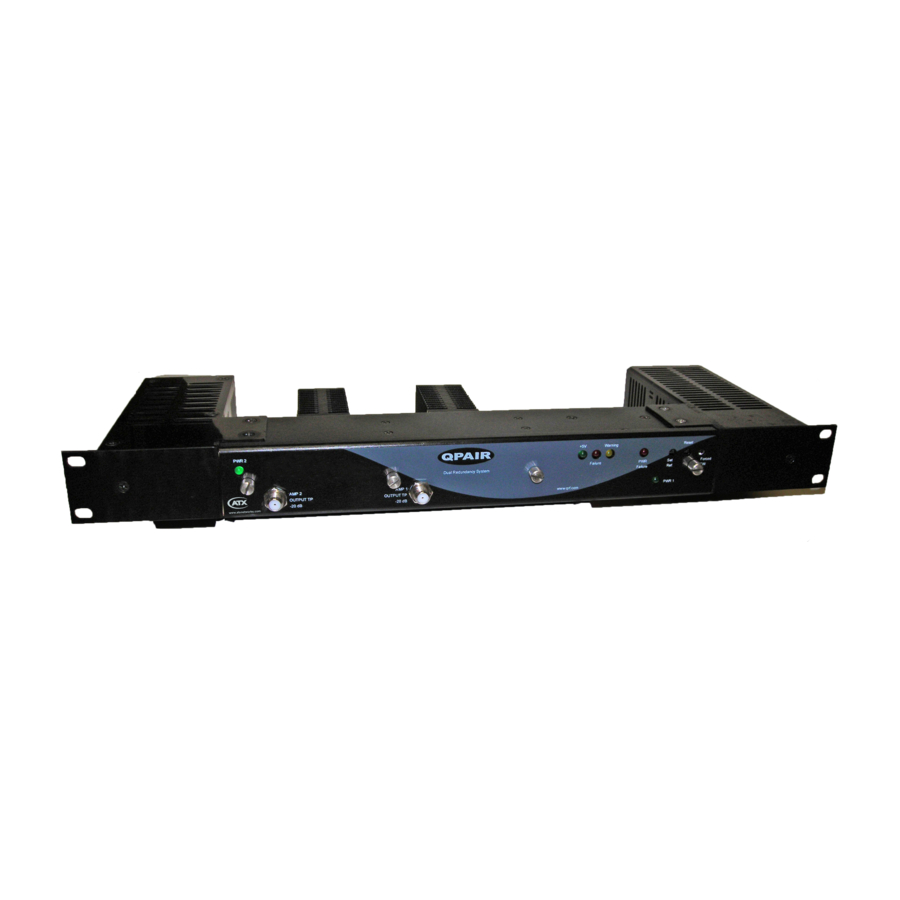
Figure #1 - QPAIR Switch/Controller Module Details
Detector
Test Point 2
Reset
Detector
Set Ref
Test Point 1
CHAPTER 3: SET-UP PROCEDURE
Forced SW
3-1
