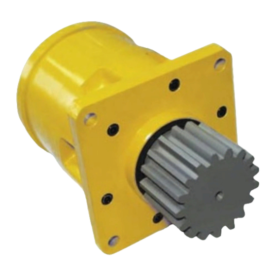
STEP 11
Re-torque bearing nut (15) to 60 - 70 lb.-ft. (80 - 94 Nm).
STEP 12
Secure bearing nut (15) by bending a lock washer (14) tab into one of
four bearing nut slots. If no tab aligns with a slot, the nut may be
tightened until one of the slots aligns with a lock washer tab.
STEP 13
Place carrier assembly (17) into ring gear (16) aligning the gear teeth.
Carrier splines mesh with splines on output shaft (1).
STEP 14
Install sun gear (18) into carrier assembly. Sun gear (18) should turn
freely by hand when assembled.
NOTE: When installing a hydraulic motor to the Power Wheel drive it is necessary to place an "O" ring or gasket (not
supplied by Auburn Gear) between the motor and the planetary drive. "O" ring sizes: SAE A 2-042, SAE B 2-155,
SAE C 2-159. Apply sealant to motor mounting bolt threads when holes in cover are thru holes.
It is recommended that the carrier assembly (17) be serviced in its entirety to protect the integrity of the Power Wheel drive.
IMPORTANT: POWER WHEEL PLANETARY DRIVES ARE SHIPPED WITHOUT LUBRICANT AND MUST BE FILLED TO THE PROPER LEVEL
PRIOR TO START UP.
Observe lubrication recommendations given by the original equipment manufacturer. When specific recommendations are not available, use mild
extreme pressure lubricant API-GL-5, No. 80 or 90 when filling the Power Wheel under normal temperature ranges between 0 - 120°F (-18 to 49°C).
Oil is to be changed after first 50 hours of operation with subsequent changes every 1000 hours or yearly, which ever comes first. Swing drive shaft
down applications - the unit should be filled so that the sun gear (18) is running in an oil bath. Swing drive shaft up applications, see note.
NOTE: This drive is equipped with a grease seal and fittings for shaft up operations. the bearing cavity must be filled
with a good grade of extreme pressure (EP) bearing grease before the unit is placed in service.
To correctly fill the bearing cavity:
1. Preferably with the drive horizontal, pump grease into cavity with a manual grease gun or low-pressure pump
system. Rotate output shaft periodically to distribute grease evenly into bearings. NOTE: On those units equipped with
an integral brake, the brake will have to be hydraulically disengaged in order to rotate the output shaft.
2. Continue pumping/rotating until grease exits relief fitting (relief pressure 11-5 psi) as soon as pumping begins. This
indicates that cavity is nearly full. Full capacity is 7-8 ounces.
3. If the grease must be added with the drive vertical, care must be taken to introduce the full 7-8 ounces to ensure that
the upper bearing is being filled with grease.
A protective film is applied to the Power Wheel at the factory to prevent rust during shipment. Additional protection may be required if the Power Wheel is to be
stored for an extended period of time.
Silastic RTV732 sealer and General Electric Silimate RTV No. 1473 or RTV No. 1503 are currently recommended for sealing gasket surfaces. Sealant should
be applied in a continuous bead, which should be centered on the surface to be sealed but should move to the inside of the hole at each bolt hole location. For
service requirements order Auburn Gear part number 604101.
Maximum intermittent output torque ................................................................................................................................................ 30,000 lb. in. (3,390 Nm)
Maximum input speed ....................................................................................................................................................................................... 3,500 RPM
Oil capacity shaft down ............................................................................................................................................................................... 38 oz. (1100 cc)
Oil capacity shaft up ........................................................................................................................................................................... Contact Auburn Gear
CARRIER ASSEMBLIES
LUBRICATION RECOMMENDATIONS
STORAGE
SEALING COMPOUND
SPECIFICATIONS
3
STEP 15
Apply a bead of silicone sealant to cover face of ring gear (16).
Secure thrust washer (19) with tangs engaged in cover (20).
N
: Washer (19) can be secured to cover (20) with a small amount
OTE
of grease or silicone sealant. Assemble cover (20) to ring gear (16).
Align cover (20) with hub flange (3) so that pipe plug holes on cover
(20) align with mounting holes in hub flange (3).
STEP 16
Install eight 5/16-18 x 1 inch bolts (21) and torque to 20 - 25 lb.-ft.
(27 - 34 Nm).
STEP 17
Fill unit so that sun gear (18) is running in an oil bath. Install pipe
plugs (8), (22) and (23).

