3onedata TNS5800 Series Panduan Instalasi Cepat - Halaman 2
Jelajahi secara online atau unduh pdf Panduan Instalasi Cepat untuk Beralih 3onedata TNS5800 Series. 3onedata TNS5800 Series 5 halaman. Layer 3 rack-mounted industrial ethernet switch
Juga untuk 3onedata TNS5800 Series: Panduan Instalasi Cepat (4 halaman), Panduan Instalasi Cepat (4 halaman), Panduan Instalasi Cepat (3 halaman), Panduan Instalasi Cepat (4 halaman)

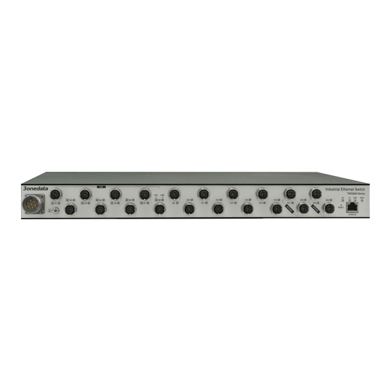
Model III, Model IV and Model V
Notice Before Mounting:
Don't place or install the device in area near water or
moisture, keep the relative humidity of the device
surrounding between 5%~95% without condensation.
Before powering on the device, check the power
specifications supported by the device to prevent device
damage due to overvoltage.
The device surface temperature is high after running;
please don't directly contact to avoid scalding.
【Install Rack-mounted Device】
Select the device mounting location to ensure
enough size.
Adopt bolts to install the mounting lugs in the
device position as figure below
Place the device on the rack surface plate; adopt 4
screws to mount the right and left mounting lugs on
the rack.
Check and confirm the product is firmly installed on
the rack, then mounting ends.
【Disassembling Device】
Power off the device.
Unscrew the fixed mounting lug screw on the rack.
Shift out the device from rack, disassembling ends.
Notice Before Powering On:
Power ON operation: First insert the power supply
terminal block into the device power supply interface,
and then plug the power supply plug and power on.
Power OFF operation: First, remove the power plug,
then remove the wiring section of terminal block. Please
pay attention to the above operation sequence.
【Power Supply Connection】
Model I and Model II
The Model I and Model II
provide two independent DC
power supply systems, P1
and
reverse connection protection and power redundancy backup.
Power interface adopts 8-pin 5.08mm pitch terminal blocks
(includes 6-pin power supply), pin definition are shown as
above. Power supply input range: 110VDC (66~156VDC)
Model III and Model V
The Model III and Model V provide two
independent DC power supply systems, P1 and
P2, which support reverse connection protection
and power redundancy backup. The power supply
interface adopts M23 7-Pin pin (male) connector. Input voltage
of power supply: 110VDC The pin definitions of M23 (male)
are shown as follows:
Pin No.
1
2
3
4
Definition
V1+
V1-
V2+
V2-
【Relay Connection】
Model I and Model II
The Model I and Model II
adopt 8-pin 5.08mm pitch
P2,
which
support
5
6
7
R1
GND R2
