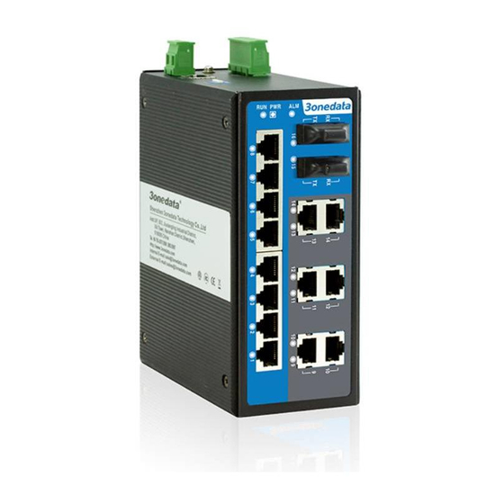
3onedata IES6116-8F-P Panduan Pengguna - Halaman 3
Jelajahi secara online atau unduh pdf Panduan Pengguna untuk Router Jaringan 3onedata IES6116-8F-P. 3onedata IES6116-8F-P 5 halaman. Managed industrial ethernet switch
Juga untuk 3onedata IES6116-8F-P: Panduan Instalasi Cepat (4 halaman)

to the closed state. The two terminal block connector are
used to detect both power failure and port failure. The two
wires attached to the Fault contacts form an open circuit
when the device has lost power supply from one of the DC
power inputs or one of the ports is failure. (Note: The AC
power switch does not support power alarm.)
【Console port】
This series product provided 1pcs procedure test port based
in serial port. It adopts RJ45 interface, located in top panel,
can configure related command through RJ45 to DB9
female cable.
【Communication connector】
10/100BaseT(X) Ethernet port
The pinout define of RJ45 port display as below, connect by
UTP or STP. The connect distance is no more than 100m.
100Mbps is used 120Ωof UTP 5, 10Mbps is used 120Ωof
UTP 3 ,4, 5.
RJ45 port support automatic MDI/MDI-X operation. can
connect the PC, Server, Converter and HUB .Pin 1,2,3,6
Corresponding connection in MDI. 1→3, 2→6, 3→1, 6→2
are used as cross wiring in the MDI-X port of Converter and
HUB. 10Base-T/100Base-TX are used in MDI/MDI-X, the
define of Pin in the table as below.
NO.
MDI signal
MDI-X signal
1
TX+
RX+
2
TX-
RX-
3
RX+
TX+
6
RX-
TX-
4, 5, 7, 8
—
—
Note:"TX±"Transmit Data±,"RX±"Receive Data±,"—" Not use.
10/100Base-T(X) MDI (straight-through cable)
10/100Base-T(X) MDI-X (Cross over cable)
MDI/MDI-X auto connection makes switch easy to use for
customers without considering the type of network cable.
100Base-FX Fiber port
- 3 -
100Base-FX full-duplex SM or MM port, SC/ST/FC type .The
fiber port must be used in pair, TX (transmit) port connect
remote switch's RX(receive) port; RX(receive) port connect
remote switch's TX(transmit) port.
The optical fiber connection supports the line to instruct
enhance the reliability of network effectively.
Suppose: If you make your own cable, we suggest labeling
the two sides of the same line with the same letter (A-to-A
and B-to-B, shown as above, or A1-to-A2 and B1-to-B2).
【LED Indicator】
LED indictor light on the front panel of product, the function
of each LED is described in the table as below.
System indication LED
LED
State
Description
Power is being supplied to
ON
PWR/
power input PWR
PWR(1~2)
Power is not being supplied to
OFF
power input PWR
When the alarm is enabled,
ON
power or the port's link is
inactive.
Alarm
Power and the port's link is
OFF
active, the alarm is disabled.
System is not running well
ON/OFF
Run
System is running well
Blinking
ON
Port connection is active
Link/ACT
Data transmitted
Blinking
1~16
Port connection is not active
OFF
【Installation】
Before installation, confirm that the work environment meet
the installation require, including the power needs and
abundant space. Whether it is close to the connection
equipment and other equipments are prepared or not.
1. Avoid in the sunshine, keep away from the heat
fountainhead or the area where in intense EMI.
