3onedata GW1104-4D Panduan Instalasi Cepat - Halaman 3
Jelajahi secara online atau unduh pdf Panduan Instalasi Cepat untuk Gerbang 3onedata GW1104-4D. 3onedata GW1104-4D 4 halaman. Modbus gateway
Step 2
Place the device on the wall as reference or
reference installation dimension; mark 2 bolt
positions on the wall.
Step 3
Nail M4 screws on the wall and keep 2mm
interspace reserved.
Step 4
Hang the device on two screws and slide
downward, then tighten the screw to enhance
stability, mounting ends.
【Wall-mounted Device Disassembling】
Step 1
Device power off.
Step 2
Unscrew the screw on the wall about 2mm.
Step 3
Lift the device upward slightly; take out the device,
disassembling ends.
Note before powering on:
Power ON operation: First insert the power supply
terminal block into the device power supply interface,
and then plug the power supply plug contact and power
on.
Power OFF operation: first unpin the power plug, then
remove the power line, please note the operation order
above.
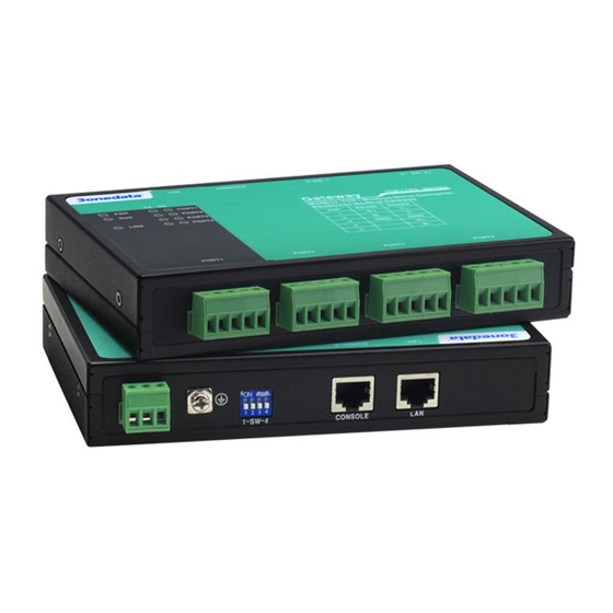
【Power Supply Connection】
9~48VDC power supply
Model I of this series provides 2-pin 5.08mm pitch
terminal block, power supply range: 9~48VDC.
12~48VDC power supply
The model II and model III of this series provide
3-Pin 5.08mm pitch terminal blocks, in which V+
and V- are DC power input, FG is the power
grounding input; The power supply supports non-polarity,
power supply range: 12~48VDC.
【DIP Switch Settings】
The model II and model III of this series provide
4-bits DIP switch for function setting, where "ON" is
enable valid terminal. The device needs to be powered on
again to change the status of DIP switch.
DIP switches definition as follows:
DIP
Definition
Operation
1
Reserved
-
2
Restore factory
Set the DIP switch to ON,
defaults
power on the device again, it
will restore to factory settings,
then turn off the DIP switch.
3
Reserved
-
4
Reserved
-
【Serial Port Connection】
RS-232 Interface
The model I of this series provides RS-232 port,
adopts RJ45 connector. The PIN definition are
1
8
as follows.
PIN
1
2
3
4
5.
RS-232 TXD RXD RTS CTS DSR GND DTR DCD
3IN1 Interface
The model II of this series provides 3IN1 serial
port, which supports RS232, RS485 and RS422
at the same time. The interface type is RJ45 and its pin
definitions are as follows:
PIN
1
RS-232 DSR RTS GND TXD RXD DCD CTS DTR
RS-485 —
RS-422 —
RS-485/ 422 interface
definitions are as follows:
PIN
1
RS-485
D+
RS-422
T+
【Checking LED Indicator】
The device provides LED indicators to monitor the device
working status with a comprehensive simplified
troubleshooting; the function of each LED is described in the
table as below:
LED
Indicate
ON
PWR
OFF
Blinking
RUN
OFF
ON
ON
6
7
8
LINK
Blinking
OFF
2
3
4
5.
6
7
—
GND —
—
D-
—
R-
GND R+
—
T-
—
The model III of this series provides 5-Pin
5.08mm pitch industrial terminal blocks.
The serial port is isolated and its pin
2
3
4
5.
D-
GND
—
—
T-
GND
R+
R-
Description
PWR is connected and running
normally
PWR is disconnected and running
abnormally
System runs normally
The system is not running or running
abnormally
System is running abnormally
Copper port has established an
active network connection.
Copper port is in a network activity
state.
Copper port has not established an
active network connection.
8
D+
T+