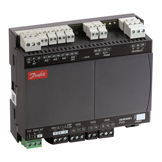
Danfoss 084B4081 Panduan Instalasi - Halaman 15
Jelajahi secara online atau unduh pdf Panduan Instalasi untuk Pengontrol Danfoss 084B4081. Danfoss 084B4081 16 halaman.

Fault message
In an error situation the alarm LED on the front will be on and the alarm relay will be activated (depending on priority).
If you push the alarm button for 3 seconds you can see the alarm report in the display.
(Alarm priorities can be changed. See the User Guide.)
Here are the messages that may appear:
Code / Alarm text via data
communication
A1/--- High t.alarm
A2/--- Low t. alarm
A4/--- Door alarm
A5/--- Max. hold time
A11/--- No Rfg. sel.
A15/--- DI1 alarm
A16/--- DI2 alarm
A45/--- Standby mode
A59/--- Case clean
AA2/ ---Refrig Leak
AA3/--- CO2 alarm
a04/--- Wrong IO cfg
--- Max. Def.Time (A,B)
E1/--- Ctrl. error
E6/--- RTC error
E20/--- Pe error
E24/--- S2 error
E25/--- S3 error
E26/--- S4 error
E27/--- S5 error
Data communication
The importance of individual alarms can be defined with a setting. The setting must be carried out in the group "Alarm destinations"
© Danfoss | DCS (vt) | 2019.10
Description
High temperature alarm
Low temperature alarm
Door alarm
The "o16" function is activated during a coordinated defrost
No refrigerant selected
DI1 alarm
DI2 alarm
Standby position (stopped refrigeration via r12 or DI input)
Appliance cleaning. Signal from DI input
A refrigerant leak detection signal is received
A refrigerant leak detection signal is received and the selected refrigerant is CO2
The configuration of inputs and outputs is incorrect
Defrost stopped based on time instead of, as wanted, on temperature. Section A / B
Faults in the controller
Check clock
Error on pressure transmitter Pe
Error on S2 sensor
Error on S3 sensor
Error on S4 sensor
Error on S5 sensor
Alarm relay groups
(P41)
1
2
4
5
7
4
4
8
8
9
9
6
5
6
6
3
3
3
3
3
AN300028324304en-000401 | 15
