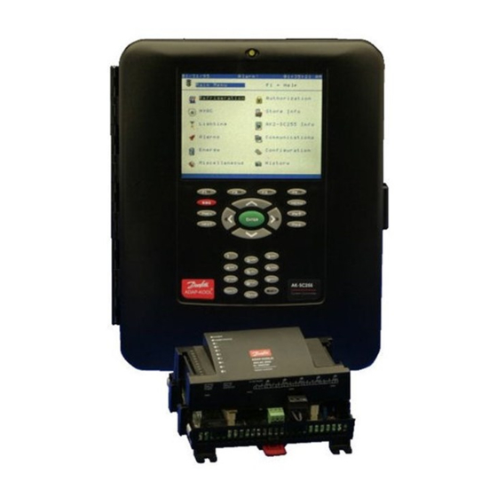
Danfoss AK-SC255 Panduan Pengguna - Halaman 3
Jelajahi secara online atau unduh pdf Panduan Pengguna untuk Pengontrol Danfoss AK-SC255. Danfoss AK-SC255 10 halaman. Com-trol local bus support
Juga untuk Danfoss AK-SC255: Panduan Instalasi (7 halaman), Panduan Pemecahan Masalah (8 halaman)

User Guide | Danfoss troubleshooting guide for supermarket electronics
1. AK-SM 800A
© Danfoss | Climate Solutions | 2022.02
Compressors not coming on with high suction
1. Check status screen of rack to see if any warnings are listed (i.e. phase loss, high discharge pressure,
oil fail, etc)
a. For high discharge pressure, check settings tab to confirm cutin/cutout values for "Disch
pressure safety" are appropriate (cutout should be higher than cutin)
b. For phase loss, oil fail, see if the device sending Danfoss a signal is tripped (i.e. phase loss
monitor, oil sensor). If so, that device needs to be investigated.
c. If the device is not tripped, check wiring and polarity in program (under Addresses on-off inputs
tab) to ensure proper config (i.e open/closed/voltage/no voltage).
2. If no warnings are listed, check staging pattern of controller (auto/manual) under Settings
a. If set to manual, # of steps should be greater than 0, and individual steps should show
compressors selected with capacity increases from one step to the next.
b. Reset the controller after reviewing this section (even if no changes made). Staging pattern
changes do not take effect until after a reset.
3. Check Address section to ensure relay address for compressor still exists, polarity correct.
4. Under status screen for rack, select "Service" and confirm no manual overrides on compressors
IO Offline
1. Verify Power to modules, Complete rescan
a. Power supply to comm modules should be 24 V AC/DC
2. Verify 'Channel Lonworks' enabled on Network Nodes screen
a. If not, enable and rescan afterwards
3. Verify term resistor switch position at AK-SM 800 is correct
a. If 1 loop from plug, switch = 'On' position
b. If 2 loops from plug, switch = 'Off' position
4. Verify EOL resistor in place at end of loop(s)
a. 120 Ω resistor or term switch in On position
b. If term switches exist on modules in middle of loop, need to be in Off position
5. Verify comm module addresses via rotary switches
6. Verify that there are no hairline shorts on the comm loop terminal
7. Verify comm loop is run as point-to-point daisy chain (no branches, etc)
8. Verify comm cable type
a. EIA RS 485 (max. 4000') for Modbus and LON RS485 devices
b. 120 Ω impedance, 42 – 75.5 pF/m capacitance, typically 22-24 AWG
9. Isolate loop in sections, rescan
a. Identifies where comm problem may be introduced
Case Controller 'Mismatch' Issue
1. Go to Network Nodes → Scan Status → Controllers
a. Locate address in list
b. Note controller version, part #, type shown
2. Go to Configuration → Control → Refrigeration → Circuits Type
a. Confirm type matches info from #1 above
b. If not, change selection in list to proper choice
c. Rescan after updating
3. Common mistakes
a. For AK-CC 550A, parameter o61 not set to match program.
i. Typically o61=2 for most setups
4. Recommendations
a. Use 'Show only scanned devices' option at top of Circuits screen to limit choices
b. If correct choice is missing from list, update system manager to latest version of firmware
AK-SM 800A Stuck on 'Verifying Nodes'
1. Go to Network Nodes, verify only channels being used are enabled
a. Disable any channels not being used
b. Reset AK-SM 800A
BC337731384771en-000301 | 3
