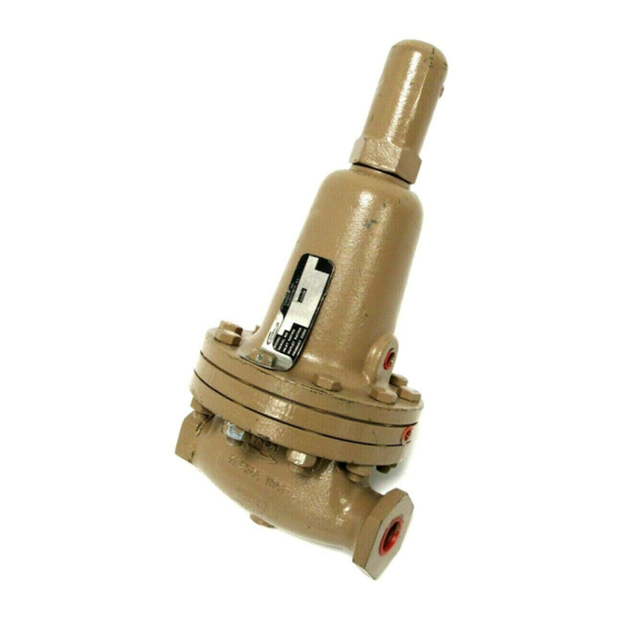
cashco 1000HP Panduan Petunjuk Pemasangan, Pengoperasian & Pemeliharaan - Halaman 4
Jelajahi secara online atau unduh pdf Panduan Petunjuk Pemasangan, Pengoperasian & Pemeliharaan untuk Pengontrol cashco 1000HP. cashco 1000HP 14 halaman. Cryogenic pressure reducing regulator
Juga untuk cashco 1000HP: Panduan Pemasangan, Pengoperasian & Pemeliharaan (17 halaman)

3. If desired, gaskets may be oiled, or coated with
gasket sealant or thread sealing com pound,
pro vid ed the sealant is compatible with
the fluid. (See below for "oxygen cleaned"
valves.)
4. Valves originally supplied as "oxygen
cleaned" (Options 1000-55, 1000-5 or 1000-
36) are as sem bled using special gasket
sealant, Fluorolube GR-362
Cashco, Inc. recommends following fac to ry
cleaning spec ification #S-1134, or equiv a lent.
Con tact factory for details.
B. Diaphragm Replacement:
1. Securely install the body (1) in a vise with the
spring chamber (2) directed upwards.
2. Relax range spring (27) by turning ad just ing
screw (6) CCW until removed from spring
chamber (2).
3. Paint or embed a match mark between body
casting (1) and spring chamber cast ing (2)
along flanged area.
4. Remove all diaphragm nuts (9) and bolts (8).
Remove nameplate (28).
5. Remove spring chamber (2), range spring
(27) and spring button (4).
NOTE: The text hereafter will refer to "pusher plate and
stud (13)" as a single part, which it is for SST trim.
Brass trim uses a separate "push er plate (5)" and a
"pusher plate stud (13)", both of which are peened
together at initial as sem bly.
6. Pry up the diaphragm(s) (20) and diaph-
ragm gasket (19) around the perimeter of the
body (1) diaphragm flange to ensure that the
diaphragm(s) (20) are not "stick ing".
7. Remove the diaphragm sub-assembly by
slid ing the pusher plate and stud (13) and
nut (11) in the direction of the regulator's
inlet, approximately 1/2"-3/4". The pusher
plate and stud (13), stud nut (10), and stud
collar (16) should disengage with the rocker
arm (14) slot. Lift vertically for the diaphragm
sub-assembly removal.
4
, or equivalent.
1
Diaphragm sub-assembly consists of items (10), (11), (12),
(13), (15), (16) and (20).
8. Place the pusher plate stud (13) in a
sepa rate vise, gripping the stud (13) on the
hex ago nal cast-in-place edges located on
the un der neath side of the pusher plate stud.
NOTE: Do not remove the stud nut (10), stud
collar (16) and the location lock ing cotter pin
(15). Loosen and remove nut (11).
9. Remove pressure plate (3) by lifting.
10. Pry loose pusher plate and stud (13) from
diaphragm(s) (20) or from pusher plate gas ket
(12). Remove the diaphragm(s) (20).
11. Remove pusher plate gasket (12) from push er
plate and stud (13).
12. Clean gasket sealing surface of pusher plate
and stud (13) thoroughly.
13. Install new pusher plate gasket (12), if
re quired, over pusher plate and stud (13).
14. Install new diaphragm(s) (20) over pusher
plate and stud (13). NOTE: Refer to the
quantity of diaphragms (20) incorporated
per the bill of materials listing. Depending on
outlet pressure level, various quantities of
metal diaphragms will be "stacked".
IOM-1000HP-Cryogenic
