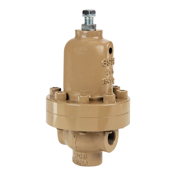
cashco 6987 Pengoperasian & Pemeliharaan Instalasi - Halaman 4
Jelajahi secara online atau unduh pdf Pengoperasian & Pemeliharaan Instalasi untuk Pengontrol cashco 6987. cashco 6987 9 halaman. Back pressure / relief regulator

9. If available, collapse the piston spring (20)
using the special tool from Figure 1. If no
special tool is available, proceed to Step 10.
10. Place new diaphragm gasket (11) and
diaphragms (10) onto body (1).
11. Place multi-purpose, high temperature grease
into depression of the pressure plate (8) and
spring buttons (4) where the ball bearing (9)
and ad just ing screw (3) bears. In the cen ter
of the di a phragms (10), place the pres sure
plate (8), ball bearing (9), spring but tons (4),
and range spring (6). Ensure spring buttons
(4) are laying flat.
12. Aligning the matchmarks, place spring
cham ber (2) over the above stacked parts.
Install flange bolts (13). Me chan i cal ly tight en
flange bolts (13) in a cross pattern that allows
the spring cham ber (2) to be pulled down
even ly. Tighten all flange bolts (13) to the
following torque value: All Sizes: 45–50 Ft-
lbs (61–68 Nm).
NOTE:
Never replace bolting (13) with
just any bolting if lost. Bolt heads and nuts
are marked with specification identification
mark ings. Use only prop er grades as
re place ments.
13. Reinstall adjusting screw (3) with locknut (5).
14. Spray liquid leak detector to test around flange
bolts (13) and body (1) / spring cham ber (2)
connection for leak age. En sure that an inlet
pressure is main tained dur ing this leak test
of at least mid-range spring level; i.e. 50-100
psig (3.4 - 6.9 Barg) range spring, 75 psig
(5.2 Barg) test pressure minimum.
C. Renewal Unit Maintenance:
1. Refer to previous pro ce dures, Sec tion VI.B.
steps 1–7 to remove all parts above the
re new al unit (17).
4
2. Remove the piston spring but ton (17.3),
piston (17.1) with piston o-ring (19), and the
piston spring (20).
3. Remove the cylinder (17.2) by turning CCW.
4. Inspect seating surfaces of the piston (17.1)
and cylinder (17.2). If necessary, relap the
seat ing sur face or replace renewal unit (17).
5. Clean all parts to be reused according to
own er's procedures. NOTE: On reg u la tors
orig i nal ly sup plied as "spe cial cleaned",
Option-55, main te nance must in clude a
level of clean li ness equal to Cash co's
clean ing stan dard #S-1134. On reg u la tors
orig i nal ly sup plied as "spe cial cleaned",
Op tion-56, main te nance must in clude a level
of cleanliness equal to Cash co's clean ing
stan dard #S-1542. Con tact fac to ry for details.
6. Lubricate the cylinder (17.2) threads lightly
with thread sealant.
(17.2) into the body (1) and impact until
approximately 100 Ft-lbs (136 Nm) torque
value is reached. This is a metal to metal seal.
7. Install the piston spring (20) into the body
(1) cavity. Place the piston o-ring (19) into
groove of piston (17.1) and install along with
the piston spring button (17.3) into the cylinder
(17.2).
8. Refer to previous procedures, Section VI.B.
steps 8–13 to replace all other parts.
9. Bench test unit for suitable operation. NOTE:
Reg u la tors are not tight shutoff devices. Even
if pressure falls below set point, a regulator
may or may not develop bubble tight shutoff.
10. Spray liquid leak detector to test around flange
bolts (13) and body (1) / spring cham ber (2)
connection for leak age. En sure that an inlet
pressure is main tained dur ing this leak test
of at least mid-range spring level; i.e. 50-100
psig (3.4 - 6.9 Barg) range spring, 75 psig
(5.2 Barg) test pressure minimum.
Install the cylinder
IOM-6987
