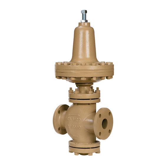
cashco 8310HP Panduan Pemasangan, Pengoperasian & Pemeliharaan - Halaman 4
Jelajahi secara online atau unduh pdf Panduan Pemasangan, Pengoperasian & Pemeliharaan untuk Pengontrol cashco 8310HP. cashco 8310HP 10 halaman. Pressure reducing regulators
Juga untuk cashco 8310HP: Panduan Pemasangan, Pengoperasian & Pemeliharaan (8 halaman)

NOTE: Never replace bolting (29) (30) with just
any bolting, if lost. Bolt heads and nuts are marked
with specification identification mark ings. Use only
proper grades as re place ments.
17. Reinstall adjusting screw (or T-bar) (32) with lock
nut (or lever) (33).
18. Spray liquid leak detector to test around bolting
(29)(30), di a phragm case (14), and spring cham ber
(13) flang es for leakage. Ensure that an outlet
pressure is main tained dur ing this leak test of at
least mid-range spring level; i.e. 10-40 psig (.69-2.8
Barg) range spring, 25 psig (1.7 Barg) test pressure
minimum.
C. Trim Inspection:
1.
To inspect the internal trim parts, refer to Section
VI.A. and B.1 through 9 for diaphragm re place ment
and proceed as follows.
2.
Secure the "flats" on the threaded end of the valve
plug assembly (12) with adjustable wrench and
remove pusher plate (17) and stem lock nut (19)
by rotating CCW (viewed from above). NOTE: Do
not rotate the valve plug assembly (12).
3.
Draw or embed a match mark between body (1)
and bottom flange (3).
4.
Loosen and remove body stud nuts (8) CCW
(viewed from bottom) to remove bottom flange (3).
In spect the bottom guide bush ing (4) for ex ces sive
wear. If worn, both the guide bushing (4) and the
bottom flange (3) must be replaced. NOTE: DO
NOT RE MOVE BON NET (2). The bonnet (2) acts
as a guide to align the valve plug assembly (12)
into the seat rings (10 and 11).
5.
Firmly grasp end of the valve plug assembly (12)
by hand and pull out of the body (1) cavity.
6.
Inspect the seating surfaces of the plug (12.1) for
nicks or excessive wear.
7.
Using a flashlight or other light source, ex am ine
the interior of body (1) cavity. Also, inspect the
seating surfaces of both the upper and lower seat
rings (10 and 11) for ex ces sive wear. If either the
plug (12.1) or the seat rings (10 and 11) are worn
and in need of re place ment, contact the fac to ry
for au tho ri za tion to return unit for re pair. NOTE:
Overhaul and replacement of trim parts is not
easily ac com plished by non-factory trained
per son nel.
8.
For Composition seat replacement:
a. Secure flats on upper plug (12.1) in a soft jawed
vise.
b. Rotate lower retainer (12.7) CCW to remove.
c. Inspect and replace lower seat (12.6). Apply
Loctite 242 (or equivalent) to threads of lower
retainer (12.7) and install lower retainer onto
4
lower plug (12.3).
d. Rotate lower plug (12.3) CCW to remove lower
plug (12.3) and Belleville washers (12.2).
e. Remove upper retainer (12.5) and upper seat
(12.4). Inspect upper seat (12.4) and replace.
f. Apply Loctite 242 (or equivalent) to threads of
upper retainer (12.5) and install on upper seat
(12.4). Install Belleville washers (12.2).
g. Apply Loctite 242 (or equivalent) to threads on
lower plug (12.3) and install onto threaded end
of upper plug (12.1).
h. Remove from vise.
9.
Remove the lower body gasket (6) and clean seal-
ing sur face thoroughly.
10. Install valve plug assembly (12) into body (1) and
place new body gasket (6) onto body (1).
11. Align match mark and replace bottom flange (3) on
body (1). Reinstall flange stud nuts (8). Me chan i-
cal ly tighten nuts (8) in al ter nat ing cross pattern
that allows bot tom flange (3) to be pulled up evenly.
Rec om mend ed torques values are as follows:
Regulator Size
1-1/2" - 2" (DN32-50)
50 Ft-lbs (68 Nm)
3" - 4" (DN80-100)
100 Ft-lbs (136 Nm)
12. Fully thread stem lock nut (19) and pusher plate (17)
on end of valve plug assembly (12). Refer to Figure
1 for correct orientation of the pusher plate (17).
13. Calibrate diaphragm (20) setting and correct valve
plug assembly (12) travel as follows:
a)
Lift and hold valve plug assembly (12) up tight
against the seats (10 and 11).
b)
Adjust the pusher plate (17) so that the gasket
surface face of the pusher plate (17) is flush
with the top of the diaphragm case (14) flange.
c)
Draw the stem lock nut (17) up tight against
the pusher plate (17) by holding "flats" milled
on push er plate (17).
14. Grasp threaded end of valve plug assembly (12) by
hand and ensure that the assembly moves freely
by lifting the valve plug as sem bly (12) in and out
of the seats (10 and 11), making sure it does not
"stick". If it does not move freely, rotate valve plug
assembly (12) CW until new position is found which
allows optimum "free vertical move ment" in and out
of seats.
15. Proceed with diaphragm (20) assembly in struc tions
in accordance with Section IV.B., steps 10 through
18. NOTE: Do not rotate valve plug as sem bly (12)
from optimum "free vertical move ment" po si tion
during final as sem bly.
Torque
Bolt Size
1/2"
5/8"
IOM-8310HP/LP-BASIC
