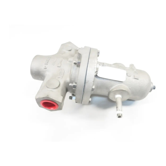
cashco DA2 Panduan Pemasangan, Pengoperasian & Pemeliharaan - Halaman 2
Jelajahi secara online atau unduh pdf Panduan Pemasangan, Pengoperasian & Pemeliharaan untuk Pengontrol cashco DA2. cashco DA2 16 halaman. Direct-acting, positive bias differential pressure reducing regulator

10. Downstream Sensing Installation Considerations
– Internal or External Sensing:
a. The regulator may be installed with internal or
external sensing. Unless otherwise specified,
the regulator is supplied by factory with internal
sensing. The regulator may be con vert ed in
the field to external sensing (see Section VII
Maintenance, Paragraph H).
b. Reference DAG-TB, Table DAG-11 for recom-
mendations for applying external pressure
sensing.
c. For internal sensing, no external line is re-
quired. For external sensing, use an external
control line. The line is connected from the port
(1/4" NPT) on the side of the body di a phragm
flange (see port 5 in Fig. 5) to a pressure tap.
The pressure tap should be located a minimum
of 10 pipe diameters downstream of the regu-
lator. It is recommended that the downstream
pressure tap be located close to the point of
use to minimize the adverse affect of variable
line losses. A tubing outer diameter of 0.25
inch is adequate for short sensing lines (less
than 4 feet). Use 3/8" tubing or 1/4" Sch 40
pipe for sensing lines of 5 to 50 feet.
d. For condensable vapors (i.e. steam) slope the
external sensing line downward 2 to 5 de grees
to outlet piping to prevent water pock ets, which
allows the diaphragm chamber to always be
self draining. The external sensing line may
be sloped upward for liquids or gases.
The proof test pressure must not exceed the
diaphragm and body rating for the regulator.
NOTE: The below ratings may be further "derated" by limitations thru the Pressure Equipment Directive (97/23/EC-May '97).
DIAPHRAGM
MATERIAL
BC, EPR
NBR
FKM, FKM+TFE, FK
3-ply (PTFE+FKM+PTFE)
METAL
Be-Cu
*Maximum setting of pressure safety device – safety relief valve or rupture disc.
**Not available for CI/CI, BRZ/CI, BRZ/BRZ, BRZ/CS, BRZ/SST, CS/CI & SST/CI constructions.
NA = NOT AVAILABLE
2
CAUTION
MAXIMUM DIAPHRAGM RATING *
BODY SIZE 1/2" - 2" (DN15-50)
STD DIAPHRAGM
CONSTRUCTION
P
MAX
2
1250
(86.1)
450
(31.0)
700
(48.2)
125
(8.6)
1500
(103)
Installation of adequate overpressure pro tec tion
is recommended to pro tect the reg u la tor from
over pres sure and all down stream equip ment
from dam age in the event of regulator failure.
A hydrostatic or pneumatic proof test is allowable un-
der the following conditions for the standard diaphragm
construction: Uniformly pressurize the valve body inlet,
valve body outlet, and loading chamber to the lesser
of the Diaphragm Proof Rating or 1.5 times the Outlet
Pressure Rating shown on the nameplate. For exam-
ple, a 1" DA2 with Cast Iron Body and Spring Chamber,
Neoprene Diaphragm (BC) has an Outlet Pressure Rat-
ing of 400 psig CWP. The lesser pressure of 1.5X 400
psig = 600 psig and the BC diaphragm proof rating of
1250 psig is 600 psig. Therefore, uniformly pressur-
izing the DA2 to 600 psig is allowable.
Model DA2 & DA7 Differential
Pressure Reducing Regulator
Recommended Piping Schematic for
Differential Pressure Reducing Station
TABLE 1
- psig (Barg)
**OPT-81 FULL DIAPHRAGM
SUPPORT
P
MAX
2
1250
(86.1)
1250
(86.1)
1250
(86.1)
125
(8.6)
NA
CAUTION
BODY SIZE 3" - 4" (DN80-100)
STD DIAPHRAGM
CONSTRUCTION
P
MAX
2
800
(55.1)
300
(20.6)
550
(37.9)
125
(8.6)
NA
IOM-DA2
