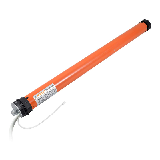
3T-Components 3T-MOTORS 3T45-50 Panduan Petunjuk Pemasangan & Pengoperasian - Halaman 16
Jelajahi secara online atau unduh pdf Panduan Petunjuk Pemasangan & Pengoperasian untuk Mesin 3T-Components 3T-MOTORS 3T45-50. 3T-Components 3T-MOTORS 3T45-50 20 halaman. Shutter / awning motors with mechanical limit switches, for shafts from 60/40 mm

INSTALLATION INSTRUCTIONS
Setting the end positions:
5
Explanation of the limit switch screws
There are 2 limit switch screws on the motor head. One limit switch screw is responsible for the „EXTEND" position, the other for the „RETURN" position.
By turning the limit switch screws with the adjustment pin, the positions of the limit switch can be adjusted.
A detailed description of the limit switch screws and the markings on the motor head can be found on page 11.
1. Setting the position „EXTEND"
Set the switch to „EXTEND", awning moves OUT.
•
Run the tubular motor in the „EXTEND" direction until the end switch-off occurs.
•
If the motor is to continue moving, turn the adjustment pin on the „EXTEND" limit switch screw in the PLUS direction until the desired position is reached.
•
2. Setting the position „RETURN"
Set the switch to „RETURN", awning moves IN.
•
Run the tubular motor in the „RETURN" direction until the end switch-off occurs.
•
If the motor is to continue moving, turn the adjustment pin on the „RETURN" limit switch screw in the PLUS direction until the desired position is reached and
•
the awning is fully retracted.
If the awning motor travels too far:
While the tubular motor is moving in the relevant direction (EXTENDING or RETURNING), turn the adjusting pin on the relevant limit switch screw in the MINUS
•
direction until the tubular motor switches off. If this is not possible, stop with the switch.
After switching off by turning the limit switch screw in the PLUS direction, allow the tube motor to move to the desired end position.
•
If this does not work, run the tube motor again in the opposite direction, stop and repeat this procedure.
•
Left installation
Power cable to rear
Limit switch screw white:
„RETURN"
Limit switch screw red:
„EXTEND"
Left installation
Power cable to front
Limit switch screw red:
„EXTEND"
Limit switch screw white:
„RETURN"
Right installation
Limit switch screw red:
Direction of rotation
Limit switch screw white:
Limit switch screw
Right installation
Limit switch screw white:
Limit switch screw red:
Direction of rotation
Limit switch screw
„RETURN"
„EXTEND"
„EXTEND"
„RETURN"
Adjustment pin is required
3T-MOTORS Tubular motors | Installation instructions
16
