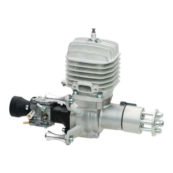
3W 3W-55Xi Panduan Pengoperasian - Halaman 7
Jelajahi secara online atau unduh pdf Panduan Pengoperasian untuk Mesin 3W 3W-55Xi. 3W 3W-55Xi 20 halaman.

Operation manual
Baffling
Deflecting of the air (baffling) to and over the cylinder(s) is highly recommended for engine cooling.
The idea is to get all of the cool air that is coming through the air intake opening(s) to hit the middle
of the cylinder(s) directly, and then be forced over the cylinder(s), creating turbulent air moving
through the cylinder(s) fins. The freely flowing, but directed and turbulent air between the fins
provides the maximum cooling for an air cooled engine. Without baffling (meaning wood or
composite dampers that direct the airflow) the air will take the path of least resistance. Some
incoming air will bounce off the cylinder(s) and the rest will escape around the cylinder(s) without
coming into contact with the cylinder(s).
Engine in pusher operation:
Important note! When engines are used operating in pusher configuration cooling gets critical and
special attention has to be given to an effective cooling method. A good cooling system layout
depends on the actual location (position) of the engine in the fuselage.
Operating temperature
To be able to check the cylinder head temperature ( CHT ) a thermo element has to be installed which fits
under the spark plug ( M 10 thread ). Optimum operating temperature range : 180° C - 220° C. In this
range piston, spark plug and combustion chamber will be free of remains. Maximum temperature of
270° C should not be exceeded. During a certain time at full speed the temperature could be 250° C.
Colour of the spark plug should be : light or middle brown. A grey / gray colour is a typical sign for over
heating. Temperatures above 270° C are critical and over 300° C, piston can seize and could completely
damage the engine.
Temperatures below 180° C create remains ( carbon ) on the piston crown. Increasing remains hit the
cylinder and cause abnormal running noises ( knocking ) which will increase the load of the needle
bearings and can destroy them. Under extreme conditions the crankshaft can break and a complete
damage of the engine will be the result.
Rear induction
Carburetors, whether front or rear, require a steady supply of fresh air. The best way to supply
air to a rear carburetor is by installing an air scoop. Some have thought to drill holes into the
fuselage near the carburetor area rather than creating an air scoop for the carburetor. This does
not work, in fact it will create a vacuum effect that will draw the air away from the carburetor! Again,
you should install an air scoop into the front of the plane which will supply air into the fuselage.
This air will then need to flow out of the fuselage. Drill exit holes into the rear area of the fuselage
for this purpose. Important: The interior of the fuselage must be sealed to prevent damage from
gasoline that sprays from the carburetor. Use a thin epoxy or other appropriate fuel proofing
method. Do not overlook this step as gasoline will melt some materials like Styrofoam very quickly.
3W Modellmotoren GmbH, Hasswiesenstrasse 22, 63322 Rödermark
www.3w-modellmotoren.de
© Copyright Qualitätsmanagement 3W, Revision 2, Page 7 from 19, valid from 22.02.2013
