Duomo BX444-Mc Instalasi dan Panduan Pengguna - Halaman 3
Jelajahi secara online atau unduh pdf Instalasi dan Panduan Pengguna untuk Pengontrol Duomo BX444-Mc. Duomo BX444-Mc 9 halaman.
Juga untuk Duomo BX444-Mc: Manual (12 halaman)

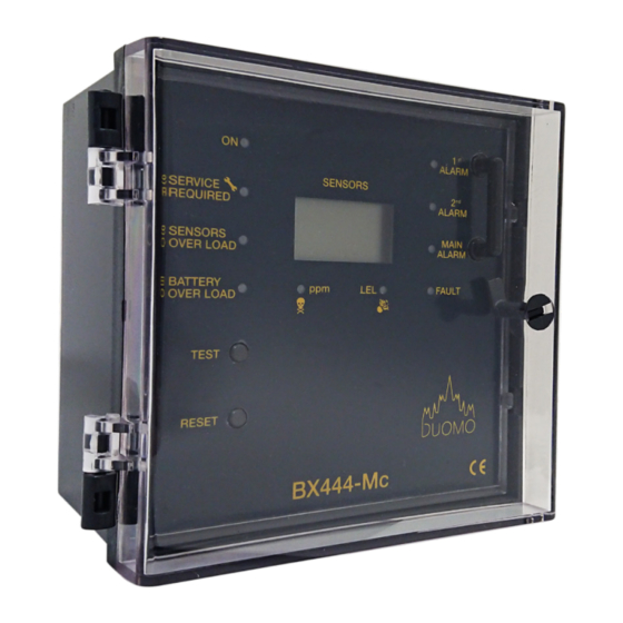
BX444-Mc Fascia & PCB Layout
Key
1.
Power On - Lights when supply voltage is applied. This light flashes during self-diagnostics start up.
2.
Service Required - This light flashes when the the scheduled service is required. This can period be set to
either 6 months or 1 year and is determined by risk assessment.
3.
Sensors Overload - When lit indicates a short circuit or overload on the sensor circuitry.
4.
Battery Overload - When lit indicates incorrect batter connection or high consumption during charging phase.
5.
Test - When pressed checks the sequence and function of the BX444-Mc (See also sensor test timer)
6.
Reset - Press this to reset the detector after an alarm or sensor fault condition.(See also sensor test timer)
7.
LCD Display - Represents the connected sensors. Each connected sensor reading scrolls automatically. Also
displays the alarm condition and status of each sensor and the BX444mC status; e.g. Test or Fault.
8.
1st Pre-Alarm - At 8% LEL concentration of gas detected. this light is lit and Pre-alarm relay 1 actuated. This relay
output de-energises as the level of detected gas exceeds 13% LEL (Natural Gas) or 200ppm (CO).
9.
2nd Pre-Alarm - At 13% LEL or 200ppm CO detected. Pre-alarm relay 2 actuated.
10.
Main Alarm - 20% LEL concentration of gas detected. Main alarm relay actuated.
11.
Fault - Indicates a short circuit, sensor fault, loss of signal or incorrect connection of the sensor.In case of a sensor
failure the LED will flash when the relevant sensor is scanned.
12.
LEL Explosive - lights when the internal DIP switch (CO/GAS) for a sensor is moved to the GAS position . As the
sensor value is displayed the corresponding light for that sensor is lit.
13.
Toxic Gas - This lights when the internal DIP switch (CO/GAS) for a sensor is moved to the CO position. As the
sensor value is displayed the corresponding light for that sensor is lit.
14. Electrical Supply and relay connection terminal plug.
15. Sensor Switches - These are used to turn the sensor on/off, determine the type of gas to be sensed,
16. Select or deselect Oxygen mode
17. Switch for setting latching or non latching in Main alarm condition
18. Continuous or a single pulse alarm relay actuation
19. Positive safety switch.
20. Emergency Stop connection terminal. (remove link when E.Stop is fitted).
21. Sensor and battery (if fitted) connection terminal.
w: www.duomo.co.uk
-
-
t: 01905 797989
-
f: 01905 774296
© Duomo (UK) Ltd. 2016
