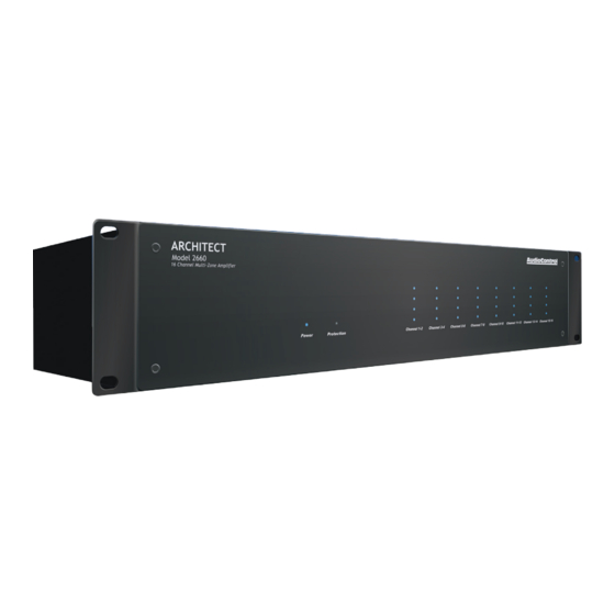
AudioControl ARCHITECT 2260 Panduan Instalasi - Halaman 7
Jelajahi secara online atau unduh pdf Panduan Instalasi untuk Penguat AudioControl ARCHITECT 2260. AudioControl ARCHITECT 2260 15 halaman. 16 channel multi-zone power amplifier

Rear Panel
Rear Panel Features
2
3
5
1
4
AC section
When rack-mounting the unit, make
sure that the power cord and the AC
power switch remain readily acces-
sible.
1. AC Input – Connect the supplied AC
power cord securely to this input. Plug
the other end into an AC mains outlet
of the correct voltage rating for your
unit. They are either 100 -120 VAC (50
– 60 Hz) or 220 – 240 VAC (50 – 60 Hz);
look at the check box to see how your
unit has been configured. The voltage
setting is not user-settable. This unit
is a class 1 device, do not defeat the
safety ground connection or use a
power cord that does not have the
safety ground pin.
2. AC Fuse – The main power supply fuse
may be checked or replaced. Make
sure that the power cord is unplugged
from the AC mains first. Then use a
flat-headed screwdriver to undo the
fuse carrier from the fuse holder.
Inspect the fuse and replace with the
exact same type indicated on the unit.
12
7
8
9 10
11
6
13
12
The use of any other type of fuse may
lead to an unsafe condition. If the fuse
blows again immediately, then unplug
the power cord and contact our fine
folks in customer service. Do not open
the unit, as there are no user-ser-
viceable parts inside, and dangerous
voltages exist.
3. AC Power Switch – This switch shuts
off the main AC power. Normally the
only time you need to turn this off is
if the system is going to be shut down
for an extended period of time. Use
the master trigger inputs to switch the
unit between standby and on.
Also turn the power switch off during
lightning storms, wind storms with
frequent power outages, or closer to
the time when the sun reaches the end
of its red giant phase and you suspect
it is about to go Supernova.
4. Ground Isolation Switch – This switch
selects the level of isolation between
the audio signal ground and the AC
earth ground. In normal operation this
switch should be in the GND Ground
position. If there is trouble with an AC
ground hum, try the other two settings
for the best operation. For safety, the
chassis is always connected to the
earth ground regardless of the switch
setting.
5. Disable Front Panel LED Ladders –
The front panel LED ladders show the
output levels of each zone. If this is a
distraction, or your pets keep getting
hypnotized, press this switch in to turn
off the LED ladders. This switch does
not affect the Power, Protection, or
Zone Status LEDs.
6. Master Trigger – The TS 1/8" connec-
tors and the 3-pin block connector are
used to turn on the unit or place it into
standby mode. Any one of these three
connections can be used as a trigger
input.
If no trigger voltage is present at any
of these trigger inputs, then the unit
will be in standby, with all zones mut-
ed. See the next page for important
details if you are not using the master
trigger.
LED indicator – This LED is blue when
the master trigger input is active, and
off when it is inactive.
3-pin connector – To remotely turn on
the unit, use either a contact closure
between the Trigger Input and the
+12V output, or an external +12V
trigger between the Trigger In and
GND terminals. The +12V output is
not designed to power other pieces of
equipment or jump start your car.
Pinout:
GND Ground
+12V Output
+12V Trigger Input
Rear Panel
1/8" TS mono jacks – These are wired
in parallel to each other, and work in
conjunction with the 3-pin connector.
Either input can receive a +12V trigger
which will turn on the unit. This will
then allow the unused jack to output
+12V that can be used to turn-on a
second unit. If the 3-pin connector is
used to trigger the unit, then both of
the 1/8" jacks can be used to provide
output triggers to other units.
Pinout:
Tip
= +12V Trigger Input
e = Ground
Sleev
Power Up Process: When a +3 to +12V
signal is sensed at the trigger input of
either of the 1/8" TS connectors, or the
3-pin connector, the rear panel master
trigger indicator LED will change from
off to blue. All the zones will be held in
standby for about 2 seconds until the
power supplies have fully charged and
performed their self-tests. During this
short process, the front panel Power
and Protection LEDs will be red. Once
this is complete, the Power LED will
turn blue and the Protection LED will
turn off.
Power Down Process: As soon as a 0V
signal is sensed at the master trigger
inputs, all zones will be muted and
placed in standby, and the rear panel
master trigger LED will change from
blue to off. The front panel Power LED
will remain on, as the main power
supplies will be still energized.
If the master trigger Inputs remain at 0V
for 2 seconds, the main power supplies
will shut off; the front panel Power LED
will change from blue to red. The Protec-
tion LED will flash red once during the
power-down process.
ARCHITECT
™
Model 2660
Installation Manual
13
