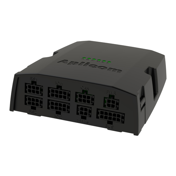
APLICOM A11 Panduan Instalasi - Halaman 6
Jelajahi secara online atau unduh pdf Panduan Instalasi untuk Pencatat Data APLICOM A11. APLICOM A11 11 halaman.

Electrical Installation
Read warnings chapter on page 9 on this document.
•
Protect power supply lines (8...32Vdc) with 3A fuse at power supply end of line.
•
Connect the cables to A11 device and peripherals as advised in the connection guide. Figure 8.
•
Install the A11 unit as far away as possible (minimum 1 metres recommended) from the car radio and its
•
antenna or other electrical devices to avoid any interference.
Additional information: Application note K505002 Cabling of Aplicom Products.
•
Avoid ground loops! It is highly recommended to connect all A11 and peripherals ground connections to a
•
single point. It is also recommended to use non-grounding antennas.
Disconnecting ground lines shall not be done while the unit is connected to power supply of the vehicle.
•
This will cause voltage leak between IO connections causing possible problems in external devices
connected to them.
External GPS antenna: Install the GPS/GLONASS antenna to a place where it has the best possible open
•
sky view. Please note that Aplicom supplied antennas are installed inside the vehicle, on dashboard, on
any surface, or windshield, depending on selected antenna type. The antennas direction to satellites must
be correct to have a good visibility of satellites. Only antennas that are separately specified and clearly
stated to be used outside of vehicle, can be installed so. Please refer to Aplicom documentation of the
antenna.
If the IGN -line is used ensure that it is connected with suitable fuse to suitable stable source. In modern
•
cars for example the lights etc. are pulse controlled and they are not suitable source for IGN –line.
A11 unit with CAN bus functionality * do not include internal bus terminator resistors (120 ).
•
If wakeup is based on motion then IGN must be connected to power supply line.
•
* CAN bus is available as option.
.
Power cable / PWR
Pin 1, PWR
Pin 2, IGN
Pin 3, PWR OUT
Pin 4, GND
Data cable / RS 1/2
Pin 1,TXD1/3
Pin2, RXD1/3
Pin3, GND
Pin4, TXD 2/4
Pin5, RXD 2/4
Pin6, GND
Red
Green
White
Black
Semo-
flex
3x0,25 mm²
Orange
Red
Black
4
3
2
1
6
5
4
3
2
1
6
