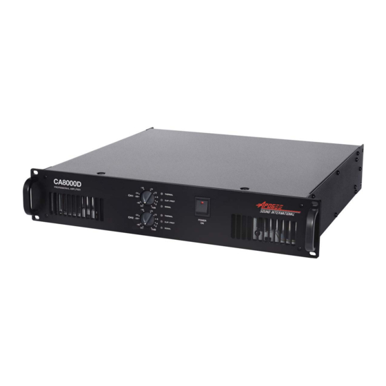
Apogee Sound CA8000DXE Panduan Instruksi Pengguna - Halaman 6
Jelajahi secara online atau unduh pdf Panduan Instruksi Pengguna untuk Penguat Apogee Sound CA8000DXE. Apogee Sound CA8000DXE 16 halaman. Professional amplifier
Juga untuk Apogee Sound CA8000DXE: Panduan Instruksi Pengguna (16 halaman)

2. Installation
2.1 Location / Assembly / Ventillation
• The CA8000D-Series amplifier is a 2 RU high (3.5") x 19'' wide rack module. It is important to recognize that
the amplifier is a heat source and should not be placed next to other equipment that is susceptible to
heat, nor should the amplifier itself be exposed to high temperatures from other nearby equipment.
• The ventilation path should always be kept free to allow fresh air to enter the ventilation tunnel. The amplifier
takes fresh air in through the rear panel, and brings it directly to the power modules, power transformer and
power capacitors. The hot air is then exhausted through the front panel. The forced air cooling system avoids
heat accumulation inside the unit and thus increases the lifespan of the electronic components.
• The unit is supplied with plastic washers so as to not damage the rack ears when the screws are tightened.
2.2 AC Power Connections (Mains)
The CA8000D-Series amplifier can be ordered for either 120VAC or 240VAC (50/60Hz) applications,
depending on the country. The label on the unit indicates the voltage that it has been configured for.
The AC power cables should not be located near the cables carrying the audio signal, as this could induce
hum into the system.
To protect the amplifier, there are five internal fuses; two situated in each power module and the fifth in the
primary transformer supply. If a fuse blows, it should be replaced by one of identical characteristics. Should
it blow again, please consult our Technical Service Department. NEVER REPLACE THE FUSE WITH
ANOTHER ONE OF A HIGHER VALUE!
CAUTION: Fuse replacement requires that the cover of the amplifier be removed, exposing the
user to potentially hazardous voltages inside the amplifier. All work must be performed by
a qualified technician.
FUSE VALUES
POWER MODULE (5x20mm)....................T12A
AC MAIN FUSE (10x38mm)......................T16A
AUXILIARY SUPPLY (5x20mm) ................T250mA
2.3 Signal Input Connections
The signal input connectors are of XLR type, electronically balanced. The pin assignment is as follows:
HOT (positive signal)
COLD (inverted signal)
GROUND
(Note: when driving the amplifier from an unbalanced source, connect pin 3 to pin 1)
The "STK OUTPUT" (stacking output) connectors are in parallel with the inputs, and are normally used to
supply the same input signal to a second amplifier. They can also be used as inputs in place of the XLR
connectors. The stacking output connectors are of the 1/4" phone jack type, with a pin assignment as follows:
HOT (positive signal)
COLD (inverted signal)
GROUND
The amplifier's input impedance is 22KΩ (balanced) with a nominal input sensitivity of 0dBV (1 volt).
The 22K impedance makes it possible to drive a group of amplifiers in parallel without loss of audio quality.
CA-8000D/E
>
Pin 2
>
Pin 3
>
Pin 1
>
Tip
>
Ring
>
Sleeve (Body)
2
