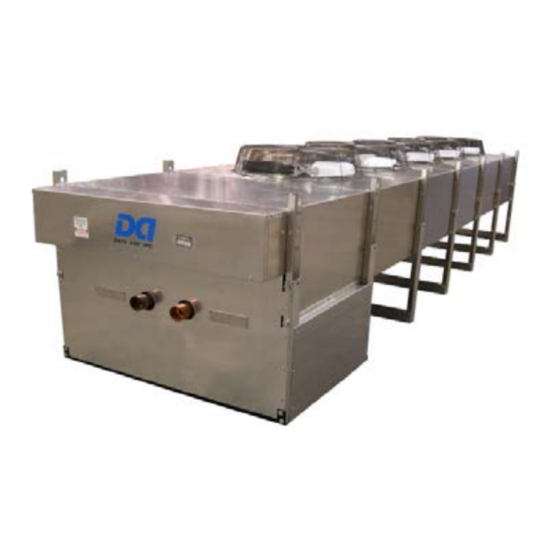
Data Aire DAFC-PB Manual dan Panduan Pengguna - Halaman 15
Jelajahi secara online atau unduh pdf Manual dan Panduan Pengguna untuk Aksesori Data Aire DAFC-PB. Data Aire DAFC-PB 20 halaman. Fluid coolers

Electrical Service
Check to be sure the service provided by the utility is sufficient to handle the additional
load imposed by the fluid coolers. Most units with secondary heat exchangers will require a
separate power source and field-provided, interconnecting control wires.
Glycol systems with fluid coolers and loose pump(s) typically require one power source
for the fluid cooler and will require one additional source for a single pump or two additional
sources for dual pumps. Systems where the pump(s) are mounted and piped integral to the
Fluid Cooler will usually require a single power source.
Nameplate Ratings
Refer to the unit electrical nameplate for equipment electrical requirements. Minimum
circuit ampacity (MCA), also known as wire sizing amps, will dictate the minimum required
wire gauge. Maximum overcurrent protection (MOP) device amps will dictate the maximum
circuit breaker or fuse size.
Grounding
The unit cabinet must have an uninterrupted true earth ground. An electrical ground wire of
adequate size must be connected to the ground lug provided inside the main electrical box.
Voltage Tolerance
The supply voltage to the unit must be within 10% (under by 5% when voltage is 208V)
of the voltage indicated on the unit electrical nameplate. Phase to phase imbalance must
not exceed 3%. The local utility company should be contacted for correction of improper line
voltage. Deviation from voltage ratings can cause premature failures and possibly void unit
warranties.
Auxiliary Control Wiring
For control wiring to the fluid coolers connect two 18 gauge wires from the electrical box
of the indoor evaporator to the electrical box of the remote fluid cooler. Follow the wiring
diagrams for each of these pieces of equipment. On most evaporators the terminals will
be #46 and #47 (older units with the Data Alarm Processor (DAP) II and III, the terminals
are #42 and #43). On most remote heat exchangers the terminals will be #39 and #40. All
control wiring on Data Aire equipment is 24 VAC or less. Refer to wiring diagrams.
Check the wiring connections in the unit control panel to ensure they are tight. Screw
terminals may become loose in transit. Tightening of wiring connections is the responsibility
of the installing contractor.
15
