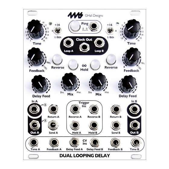
4ms Company Dual Looping Delay Panduan Pengguna - Halaman 15
Jelajahi secara online atau unduh pdf Panduan Pengguna untuk Pedal Musik 4ms Company Dual Looping Delay. 4ms Company Dual Looping Delay 20 halaman.
Juga untuk 4ms Company Dual Looping Delay: Catatan Rilis (10 halaman)

Special Features
Bus Clock Jumper
Connect the jumper on the upper position ("RECV") to receive a ping clock from the clock bus. The
signal on the bus clock will be automatically patched to the Ping jack. By plugging a cable into the Ping
jack, the bus clock will be disconnected from the Looping Delay.
Note: When receiving a bus clock, you must stop the external bus clock or patch a dummy cable into
the Ping jack in order to use the Ping tap button.
Bus Clock Disabled:
Remove the jumper completely to disable clock bus support. This is the factory-default. It's safe to
connect the jumper to only one pin.
System Settings Mode
System Settings Mode allows you to change the way some features of the Looping Delay behave. For
novice users, these are not necessary to modify, but advanced users may wish to explore.
It's recommended that new users get familiar with the Looping Delay operation using default system
settings before making changes!
In order to enter or exit System Settings Mode, the Time switch must be flipped up.
To enter, flip the Time switch up and hold down all three buttons for two seconds. Release the buttons
when you see all the buttons' lights turn off.
There are two ways to exit System Settings Mode:
1) Exiting while temporarily saving changes is similar to the process of entering System Settings
Mode. Flip the Time switch up and briefly press all three buttons. Make sure to release the buttons
within 2 seconds or less. The changes you made will stay in effect until you power the module down.
The next time you power it up, the previous settings will be restored.
2) To exit while permanently saving changes, turn the Time switch up and hold down all three buttons
for 2 seconds. The Reverse and Inf. Hold button lights will flash rapidly to confirm saving. Settings will
be saved even after powering down.
Bus Clock is a 1:1 clock that runs along the Gate pin of the power system.
Modules such as the 4ms QCD, RCD, SCM+, PEG, DLD, SWN, and MiniPEG
are compatible with the clock bus system. To use the Looping Delay on a bus
clock system, install the jumper in one of two positions:
Bus Clock Send:
Connect the jumper on the lower position ("SEND") to send the master clock
from the Looping Delay to the clock bus. The clock will be identical (but
separately buffered) as the signal on the Clock Out jack. It is not recommended
to have more than one device sending on the same clock bus system.
Bus Clock Receive:
Page
15
of
20
