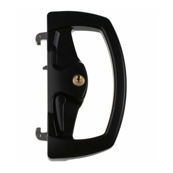
Austral Lock YARRA DEADLOCK Series Ilustrasi Petunjuk Pemasangan
Jelajahi secara online atau unduh pdf Ilustrasi Petunjuk Pemasangan untuk Kunci Austral Lock YARRA DEADLOCK Series. Austral Lock YARRA DEADLOCK Series 2 halaman.

YARRA DEADLOCK SERIES
Illustrated Fitting Instructions for Yarra Deadlock using:
Illustrated fitting instructions
YARRA VIEW
STANDARD OUTER PULL
Austral
Lock
These instructions describe the steps to install a Yarra View (or Yarra Ridge)
deadlock with a Yarra View Standard Outer Pull. Read through all instruction
steps before beginning installation. When replacing an old lock, modify the
existing installation holes in the door stile and jamb if necessary.
For optimal installation, ensure the door is rolling smoothly and closing
parallel into the jamb by lubricating and adjusting the rollers. Close the
door and lightly mark the door stile at the edge of the overlapping jamb.
Prepare three 9.0mm holes in the door stile as dimensioned below in
Figure A. Ensure the holes are straight and free from burrs.
Door Stile
Door Jamb
Mark and measure
from this edge
Mark
9.0 mm
Door Stile
If a cylinder is not being used in the Outer Pull, proceed to STEP4.
To remove a Cylinder Plug and install a Keyed Cylinder into the Outer Pull,
remove the Retaining Plate and remove the Cylinder Plug. (refer Figure B)
The Cylinder Plug can be discarded.
Use the table in Figure C below to determine the required Spindle length.
NOTE: If using packer(s), add the total packing thickness to the door
thickness, then use this value in the table below.
Use pliers or a vice to carefully break off the required number of pre-notched
portions of the Spindle to suit the door thickness.
Retaining Plate
Cylinder Plug
Exterior
Interior
Figure B
Total Width
(Door thickness + Packer thickness)
46.4 to 40.2mm
14.0 mm
40.1 to 33.9mm
33.8 to 27.6mm
27.5 to 21.3mm
41.0 mm
41.0 mm
Figure C
Figure A
Outer Pull
Spindle preparation
Break off '0' portions
Break off '1' portion
Break off '2' portions
Break off '3' portions
Discard
Notch
Spindle
Install the Keyed Cylinder into the Outer Pull
Insert the Spindle through the hole in the Retaining plate, and re-assemble
the Retaining Plate into the Outer Pull. It may be necessary to rotate the
Spindle to find its position between the Drive Pins on the Cylinder.
Push the Retaining Plate in firmly so it will not come loose while assembling
the Outer Pull onto the door.
Retaining Plate
Keyed Cylinder
Figure D
Several pairs of Fixing Screws are provided to suit different door
thicknesses. Use the table below to identify which are the correct
length Fixing Screws.
NOTE: If using packer(s), add the total packing thickness to the door
thickness, then use this value in the table below.
Total Width
(Door thickness + Packer thickness)
46.4 to 40.2mm
40.1 to 33.9mm
33.8 to 27.6mm
27.5 to 21.3mm
Figure E
PLEASE TURN PAGE FOR INSTALLATION STEPS 5 - 8
(Pk0024) YV Instructions- YV Standard Outer Pull (Trade A4) R5.cdr
Spindle
Cylinder Drive Pins
Outer Pull
Screw selection
1 ¾" Fixing Screw
1 ½" Fixing Screw
1 ¼" Fixing Screw
1" Fixing Screw
