GAC ACE295 Series Panduan Cepat - Halaman 4
Jelajahi secara online atau unduh pdf Panduan Cepat untuk Pengontrol GAC ACE295 Series. GAC ACE295 Series 4 halaman. Integrated pump mounted electric actuator
5
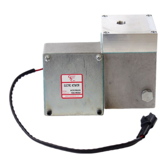
WIRING
he EC1000 or EC1010 electrical connector that mates with the actuator must be pre-wired in a configuration to match the system voltage.
T
Cable Harnesses CH1215, and CH1515 are available from GAC. Refer to MATING HARDWARE in section 2 ,SPECIFICATIONS.
CABLE HARNESS
Fabricate a cable harness to connect the speed control unit to the actuator. The
recommended wire size of the cable harness is 18 gauge (1 mm
system.
larger gauge wire is necessary for cable lengths greater than 12 ft (4 m).
The ACB295F-24 version of the actuator includes a rack position sensor. A GAC
speed control unit that includes fuel management electronics is required to interface
with this sensor. See your speed controller installation manual for wiring information.
ACE295F-24
6
TROUBLESHOOTING
The engine should be equipped with an independent shut down device to prevent overspeed which can cause equipment damage or
personal injury.
If the governor system fails to operate, make the following tests at the actuator mounted connector while moving the actuator through
its stroke.
TROUBLESHOOTING TEST
1.
Energize the actuator to full fuel with the speed controller.
2.
Manually move the actuator through its range using the stop lever. No binding or sticking should occur.
3.
If the actuator passes these tests, the problem is elsewhere in the system. Refer to the troubleshooting section of the speed control unit's
installation manual.
) for a 24 V DC
2
ACE295-24
4
HARNESS
PIN
SIGNAL
1
+ 5 V DC
2
GND
4
OUT
ACE295 Series Actuator 3-2020-C
Governors America Corp. © 2020 Copyright All Rights Reserved
PIB4160