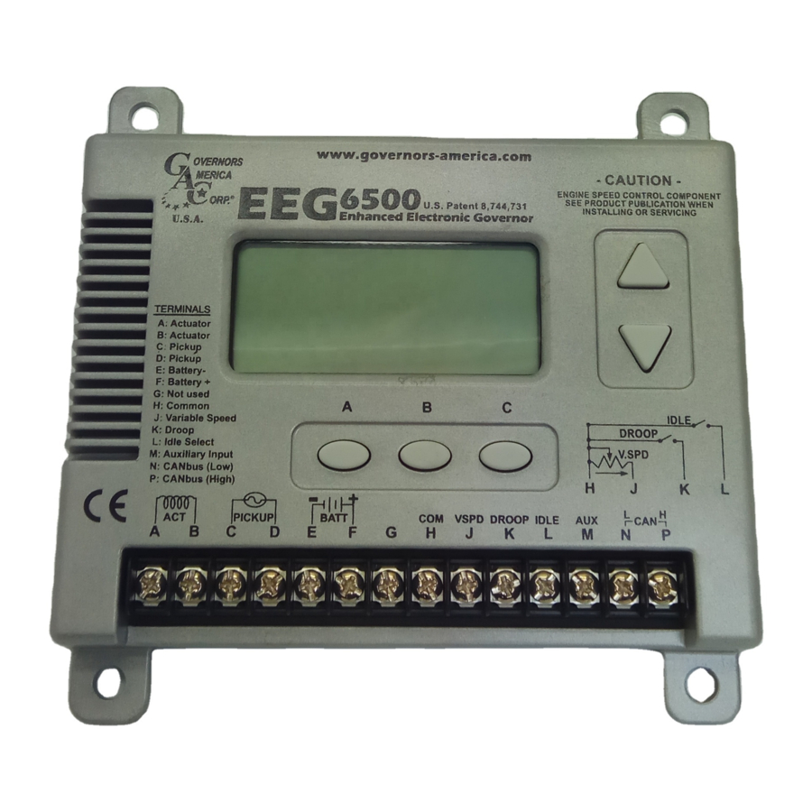
GAC EEG6500 Manual - Halaman 6
Jelajahi secara online atau unduh pdf Manual untuk Pengontrol GAC EEG6500. GAC EEG6500 9 halaman. Enhanced electronic governor with quikset display

11
FAULT CODES
CODE
1
Actuator over current (continuous)
Loss of speed signal (inc/dec in speed by more than
2
64Hz in 4ms, 16KHz/s)
Over speed (speed exceeds OVER SPEED setting
3
for 12 ms)
Variable Speed settings are reversed. V.SPEED is
203
lower than SPEED.
No potentiometer/signal detected on variable speed
206
input when VSPD enabled.
241
New software loaded. Configuration not compatible.
251
Software loaded on incompatible hardware.
307
FLCU / NLCU Setting invalid
IMPORTANT
For all other codes, note the condition and contact GAC. The WARNING indicator will blink and failures will cause a system shut down.
12
J1939 CAN INFO
J1939 Address: 26
PGN
DEFINITION
61444
Engine Speed
13
SYSTEM TROUBLESHOOTING
If the engine governing system does not function, the fault may be determined by performing the voltage tests described in Steps 1 through 3. Positive (+) and negative (-) refer to meter
polarity. Should normal values be indicated during troubleshooting steps, then the fault may be with the actuator or the wiring to the actuator. Tests are performed with battery power on and
the engine off, except where noted. See actuator publication for testing procedure on the actuator.
STEP
WIRES
NORMAL READING
Battery Supply
1
F(+) & E(-)
(12 or 24V DC)
1.0V AC RMS min.
2
C & D
While Cranking
1.0 - 2.0V DC
3
F(+) & A(-)
While Cranking
INSTABILITY
SYMPTOM
The engine seems to jitter with
Fast Periodic
a 3Hz or faster irregularity of
speed.
Speed irregularity below 3Hz.
Slow Periodic
(Sometimes severe)
Non-Periodic
Erratic Engine Behavior
ADVANCED MENU PARAMETERS (CONFIGURABLE)
CAUSE
Engine speed in RPM
1.
DC battery power not connected. Check for blown fuse
Voltage
2.
Low battery voltage
3.
Wiring error
1.
Gap between speed sensor and gear teeth too great
2.
Improper or defective wiring to the speed sensor
3.
Resistance between D and C should be 130 to 1200 ohms.
4.
Defective speed sensor.
1.
SPEED or IDLE parameter set incorrectly
2.
CRANK or START FUEL set incorrectly
3.
Short/open in actuator wiring
4.
Defective speed control
5.
Defective actuator, see Actuator Troubleshooting
1.
Readjust the GAIN and STABILITY for optimum control.
2.
In extreme cases, change the DEADTIME parameter.
1.
Check fuel system linkage during engine operation for:
a. binding
b. high friction
c. poor linkage
2.
DEADTIME Parameter set too high.
1. Increasing the GAIN should reduce the instability but not totally correct it. If this is the case, there is most
likely a problem with the engine itself.
Check for:
a. engine mis-firings
b. an erratic fuel system
c. load changes on the generator set voltage regulator.
If unsuccessful in solving instability, contact GAC for assistance.
[email protected] or call: 1-413-233-1888
EFFECT
Actuator turned off for 30 sec.
WARNING indicator blinks then system shutdown
WARNING and OVER SPEED indicators blink
then system shutdown.
WARNING indicator blinks, speed set to V.SPEED
setting, variable speed input unresponsive.
WARNING indicator blinks, speed set to SPEED
setting.
Default configuration used.
WARNING indicator blinks then System shutdown.
Load calculation done with 0.5 & 4.0 amp values
NOTES
SYSTEM INOPERATIVE
PROBABLE CAUSE OF ABNORMAL READING
INSTABILITY
PROBABLE CAUSE OF ABNORMAL READING
EEG6500 Enhanced Electronic Governor 05.09.18
6
CUSTOMER ACTION
Check actuator wiring.
Check speed pickup.
Check fuel system as well as
OVER SPEED, SPEED, and V.SPEED
Flip V.SPEED and SPEED settings.
Check potentiometer wiring.
Reset configuration.
Return unit to GAC
Adjust NLCU / FLCU per section 9
PIB 5010 F
© 2018 Copyright All Rights Reserved
