GAC EEG6550 Series Manual - Halaman 11
Jelajahi secara online atau unduh pdf Manual untuk Beralih GAC EEG6550 Series. GAC EEG6550 Series 13 halaman. Enhanced electronic governor
14
14
SYSTEM TROUBLESHOOTING
SYSTEM TROUBLESHOOTING
SYSTem InoPeraTIve
If the engine governing system does not function, the fault may be determined by performing the voltage tests described in Steps 1
through 3. Positive (+) and negative (-) refer to meter polarity. Should normal values be indicated during troubleshooting steps, then the
fault may be with the actuator or the wiring to the actuator. Tests are performed with battery power on and the engine off, except where
noted. See your actuators installation manual for testing procedures for that actuator.
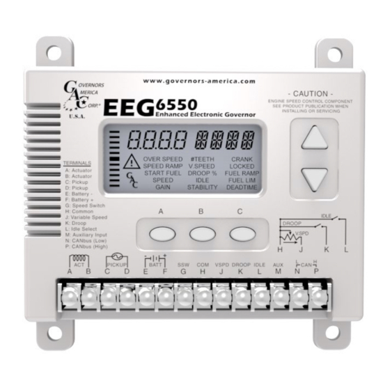
STeP
WIreS
normal reaDInG
Battery Supply
1
F(+) & E(-)
(12 or 24V DC)
1.0V AC RMS min.
2
C & D
While Cranking
1.0 - 2.0V DC
3
F(+) & A(-)
While Cranking
InSTaBIlITY
InSTaBIlITY
SYmPTom
The engine seems to jitter with
Fast Periodic
a 3Hz or faster irregularity of
speed.
Speed irregularity below 3Hz.
Slow Periodic
(Sometimes severe)
Non-Periodic
Erratic Engine Behavior
UnSaTISfacTorY Performance
SYmPTom
Engine Over Speeds
Over Speed shuts down en-
gine before or after running
speed is reached
Over Speed shuts down
engine before running
speed is reached
1.
DC battery power not connected. Check for blown fuse
2.
Low battery voltage
Voltage
3.
Wiring error
1.
Gap between speed sensor and gear teeth too great
2.
Improper or defective wiring to the speed sensor
3.
Resistance between Terminals D and C should be 130 to 1200 Ω.
4.
Defective speed sensor.
1.
SPEED or IDLE parameter set incorrectly
2.
CRANK or START FUEL set incorrectly
3.
Short/open in actuator wiring
4.
Defective speed control
5.
Defective actuator, see your actuator troubleshooting documentation.
1.
Readjust the GAIN and STABILITY for optimum control.
2.
In extreme cases, change the DEADTIME parameter.
1.
Check fuel system linkage during engine operation for:
a. binding
b. high friction
c. poor linkage
2.
DEADTIME Parameter set too high.
1. Increasing the GAIN should reduce the instability but not totally correct it. If this is the case, there
is most likely a problem with the engine itself. Check for:
a. engine mis-firings
b. an erratic fuel system
c. load changes on the generator set voltage regulator.
normal reaDInG
1. Do Not Crank. Apply DC power to
the governor system.
2. Manually hold the engine at the
desired running speed. Measure the
DC voltage between Terminals A(-)
& F(+) on the speed control unit.
3. Check #TEETH parameter.
Examine the SPEED and OVER
1.
SPEED operating parameters for
the engine
1. Check resistance between Termi-
nals C&D. Should be 130 to 1200
Ω. See specific Magnetic Pick-up
data for resistance.
ProBaBle caUSe of aBnormal reaDInG
ProBaBle caUSe of aBnormal reaDInG
ProBaBle caUSe of aBnormal reaDInG
1.
If the actuator is at minimum fuel position and there exists an erroneous
speed signal, then check speed sensor.
1.
If the voltage reading is
1.0 to 2.0 V DC:
a. SPEED parameter set above desired speed
b. Defective speed control unit
2.
If voltage reading is > 2.0 V DC then check for:
a. actuator binding
b. linkage binding
3.
If the voltage reading is below 1.0 V DC then defective speed control
unit
1.
Incorrect tooth count entered.
1.
SPEED parameter set too high.
2.
OVER SPEED set too close to SPEED.
3.
Check SPEED RAMP parameter.
4.
Check if VSPD is ON by mistake
5.
Check if AUx is ON by mistake
6.
Actuator or linkage binding.
Speed Control unit defective.
Gain too low.
1.
OVER SPEED set too low
2.
If the speed sensor signal is erroneous, then check the wiring.
EEG6550 Enhanced Electronic Governor 5-2020-A1
11
Governors America Corp. © 2020 Copyright All Rights Reserved
PIB1118