Gage Bilt GB54B Manual Petunjuk Asli - Halaman 8
Jelajahi secara online atau unduh pdf Manual Petunjuk Asli untuk Peralatan Gage Bilt GB54B. Gage Bilt GB54B 16 halaman. Pneumatic installation tool
Juga untuk Gage Bilt GB54B: Panduan Pengguna (9 halaman)
WARNING:
Only qualified and trained operators shall install, adjust or use the assembly power tool for non-threaded
mechanical fasteners.
WARNING:
Operator
WARNING:
It is required that eye protection, hearing protection and safety boots be worn at all times while handling this
equipment.
WARNING:
The users or the user's employer must assess specific risks that could be present as a result after each use
based on their application.
● Ensure there is adequate clearance for tool and operator's hands before proceeding. Keep fingers clear of any
moving parts. Keep fingers clear from fasteners and installed materials. Severe personal injury may result.
● Verify
●
Ensure that there are no electrical cables, gas pipes, etc., which can cause a hazard if damaged by the tool.
WARNING:
Do not actuate fastener in the air. Personal injury from fastener ejecting may occur.
WARNING:
Air is exhausted from the bottom of the tool. Direct bottom of the tool (exhausted air) away from operator, other
persons working in the vicinity, foreign matter and liquid.
WARNING:
Do not carry from hoses or use as a hammer.
WARNING:
Do not use in explosive atmosphere.
WARNING:
Ensure air hose is securely connected to avoid possible hose whipping.
WARNING:
Always disconnect air supply when tool is not in use to prevent accidental start-up.
WARNING:
Ensure there is adequate clearance for tool and operator hands.
WARNING:
Do not operate this tool without deflector, pintail catcher bag or pintail collection bottle in place.
CAUTION:
Do not use beyond the design intent.
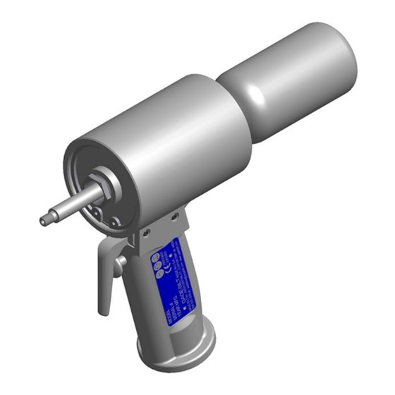
The tool is shipped with a red plastic plug in the air inlet connector. The connector has a 1/4-18 female pipe thread to accept end-user
air hose fitting. Air is exhausted through a port in the side of the tool. To redirect air exhaust to rear of tool, remove plug (401816) from
rear exhaust hole. If changing exhaust back to side, we recommend applying Vibra-tite® to plug (401816) before installation.
(See page 7 for air exhaust options).
1. Remove red plastic shipping plug from handle (510422) and install 1/4" (6.3 mm) air fitting into bottom of handle (510422). Only use an
air supply set at 90 psi-100 psi (6.2 bar-6.9 bar) equipped with a filter-regulator to prevent wear.
2. Connect tool to air hose with 90 psi. (6.2 bar) using clean, dry air. 3/8" (9.52 mm) minimum diameter air line is recommended. Cycle
tool a few times by depressing and releasing actuator assembly (510127).
3. Disconnect air hose from tool.
4. Select proper Nose Assembly, screw collet and anvil onto the tool and attach securely. (See proper data sheet for further instructions).
5. Connect air supply.
6. To install screw-on pulling head: While keeping internal components of pulling head forward in the nose assembly start threading
in the anvil holder, continue threading in until internal component starts to thread onto the drawbolt (541117). Thread nose assembly
in until nose assembly bottoms out. After nose assembly is completely threaded onto tool, back off nose until flat is in the desired
position and tighten locknut.
GB54B S/N: 1088 AND ABOVE
PLEASE CONTACT GAGE BILT FOR ALL OTHER SERIAL NUMBERS.
HOW TO SET-UP THE GB54B
MUST
read and understand all warnings and cautions.
the air lines and/or hydraulic hoses are not a trip hazard.
8
Rev. 10/22