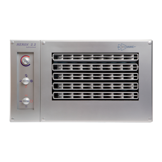
Aircommand HERON 2.2 Panduan Petunjuk Instalasi - Halaman 3
Jelajahi secara online atau unduh pdf Panduan Petunjuk Instalasi untuk Pendingin Udara Aircommand HERON 2.2. Aircommand HERON 2.2 10 halaman.
Juga untuk Aircommand HERON 2.2: Panduan Pemilik (17 halaman)

PIPE INSTALLATION & CONTROL WIRING
The pipe work consists of a
3
/
" tube (return gas) running between the Con/set and
8
3
the A/H. The
/
" line must be insulated with 10 x 10
8
mm foam rubber insulation.
Connection is made at the back of the Con/set. Pipe
work may be run internally to the A/H, or may be run
through holes in the floor and run externally to a
convenient re-entry point, or the pipes may be built into
the wallspace during van construction. NB. Pipework
installed in walls must be well insulated to avoid
"sweating" and possible long term moisture damage.
The control wiring will normally follow the pipework
and be taped to it. NB. If the control cable is to be run
externally, then it must be run in a suitable conduit.
Now refer to the A/H installation, after which we return
to the Con/set to open up the refrigeration circuit and fit
the louvre panel.
AIR HANDLER INSTALLATION
If possible, the A/H should be installed at either end of the van, such that unimpeded air flow is obtained
down the length of the van.
If this is not possible, install the A/H in as central a position as possible.
5 MOST IMPORTANT POINTS THAT MUST BE SATISFIED
1. The distance from the back of the cupboard to the back of the A/H must not be less than 90 mm
to allow proper air entry to the fan. Insufficient gap will also increase the noise level.
2. Two separate return air grilles/filters are supplied, and must be installed. If only one is used, this
will reduce the air volume back to the fan and hence the capacity of the airconditioner.
3. The airhandler must be fitted allowing a minimum space of 25 mm between the right hand of the
A/H and the wall, and likewise 25 mm between the top of the A/H and the inside top of cupboard.
4. The return air grilles/filters, should be fitted as far back as is possible to provide a more direct
path for air to flow back to the fan.
5. The A/H has a condensate drain underneath. This drain must continuously "fall" from the outlet. It
is recommended that the bottom of the A/H be 70 mm above the bottom of the cupboard, to allow
adequate fall.
A lesser amount is ok, provided much care is exercised to avoid "humps" that will result in
airlocks and backup & overflow of condensate.
It is recommended that the minimum cupboard dimensions be
The airhandler has been designed to operate in a cupboard or enclosure as described on this page.
Under no circumstances is the resistance to airflow to be increased by ducting the supply or return air.
Refer to fig. 7 & 8 and the full size template provided in the kit
1
/
" tube (liquid line), and a
4
525 wide x 320 high x 300 deep.
90 mm min.
Refrig. pipes cross
back of enclosure
and come round on
LH. side to give flexibility
2 return air filter
assy. inset to bottom
of cupboard
Section Detail
Refrig. liner
Facia
Return air filter
Drain
3
75 mm between pan of unit an
bottom to allow for drain fall
Refrig. lines, drain hose,
electrical cable
(cover with moulding)
Figure 6
