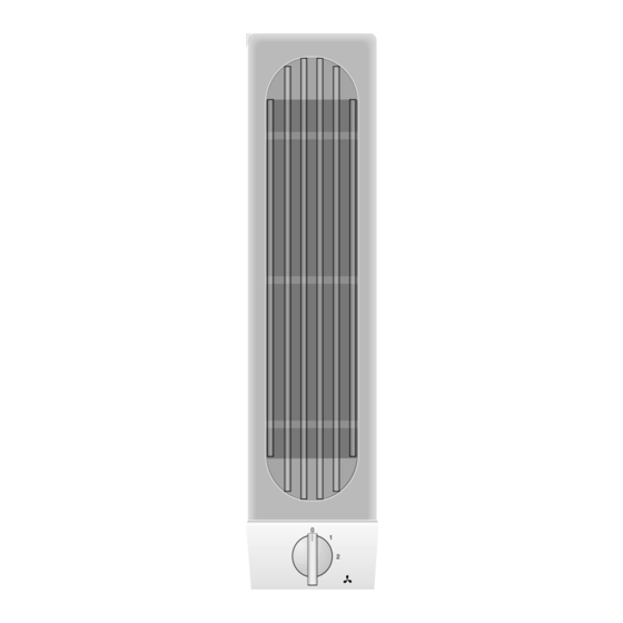
Gaggenau VL040-707 Manual Petunjuk Pengoperasian dan Perakitan - Halaman 11
Jelajahi secara online atau unduh pdf Manual Petunjuk Pengoperasian dan Perakitan untuk Kap Ventilasi Gaggenau VL040-707. Gaggenau VL040-707 15 halaman. Hob ventilator
Juga untuk Gaggenau VL040-707: Manual Petunjuk Pengoperasian dan Perakitan (15 halaman)

The appliance must only be connected by
an authorised specialist. The specialist is
responsible for perfect functioning of the appliance
at its installation location. He must explain the
operating principle of the appliance to the user with
reference to the operating instructions. He must
explain to the user how the appliance can be
isolated from the mains whenever required.
The exhaust air can be routed into a ventilation
shaft or directly into the open through the outside
wall. Adequate incoming air must be ensured
whenever the hob ventilator is operated in the
exhaust air mode and firing systems dependent
on a chimney are operated at the same time.
It is not allowed to pass the exhaust air into a flue
or exhaust air chimney that is in operation or into a
shaft that is linked to the heating basement. Consult
the chimney sweep responsible for your district
whenever you wish to pass the exhaust air into a
chimney that is not in operation.
Adequate incoming air must be ensured if a
wood, coal, gas or oil heater or an open hearth is
operated in the same room as the one in which
the wall hood is installed.
Adequate ventilation of the room must be
ensured whenever a hob ventilator is operated
simultaneously with devices that are operated with
non-electrical energy. Official regulations must be
observed with regard to removal of the exhaust air.
The applicable regulations of the power
supply companies and the regional construction
regulations must be observed when installing the
hob ventilator.
The lateral distance from the appliance installed
next to it must amount to 8 mm.
Safe operation is possible whenever the partial
vacuum in the place where the firing equipment is
installed does not exceed 4 Pa (0.04 mbar). This
can be achieved whenever the air needed for
combustion is able to enter through openings that
10
All manuals and user guides at all-guides.com
cannot be sealed, for example in doors, windows,
incoming/exhaust air wall boxes or other technical
means.
Flexible aluminium pipes, corrosion-protected
sheet metal pipes and exhaust air pipes whose
material conforms to fire B1 in accordance with
DIN 4102 can be used. Exhaust air pipes should
have a nominal diameter of 125 mm.
After installation, plug the connecting cable plug
in an accessible socket. If the plug can no longer be
removed after installation, isolation of all poles from
the mains must be ensured by means of an acces-
sible isolator with a contact spacing of at least 3 mm.
If two Vario appliances are used, the hob
ventilator must be installed between the
appliances. If 4-plate hobs are used, it is
recommended to place two ventilation devices to
the left and right of the hob. Owing to the high air
output, an adequate supply of air is required.
If you have installed the hob extractors VL 040/041
next to a gas appliance, each has to be fitted with
an air baffle LS 041 while cooking.
To prevent the ingress of water, e.g. condensate
or rain water from an uncovered exhaust air shaft,
our condensate separator RV 050-150 must be
installed in the proximity of the hob ventilator. The
condensate separator must still be accessible after
installation.
Electrical connection
Pay attention to the rating plate data.
If damaged, the mains cable must be replaced by a
special mains connecting cable. The mains connec-
ting cable must only be connected by the manu-
facturer or the manufacturer's after-sales service.
When connecting the power supply cord to the
receptacle located below the cooktop surface, the
cord is to be:
– Routed beneath the appliance; and
– Routed away from heat generated by the cooktop.
