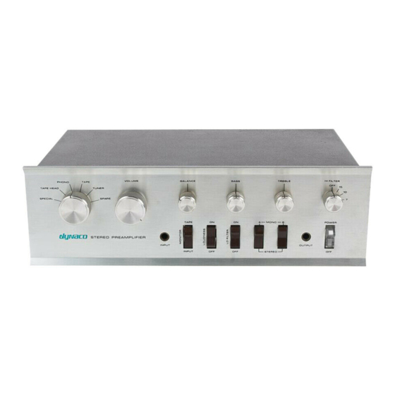
DYNACO PAT-4 Panduan Perakitan - Halaman 10
Jelajahi secara online atau unduh pdf Panduan Perakitan untuk Penguat DYNACO PAT-4. DYNACO PAT-4 16 halaman. Power supply
Juga untuk DYNACO PAT-4: Panduan Perakitan (20 halaman)

Orient the transistors so the position of the metal tab matches the silk-screen outline.
Solder the outside leads first and assure that the transistors are straight, then solder the
center lead. Let the shoulders of the transistors leads set their height above the board
Designation Type
Q3
TIP31C
Q6
TIP32C
Inspect your work for the absence of solder bridges when you're done.
Install the Capacitors
Install the polarized electrolytic capacitors. Note that + sign on the silk-screen shows
where the positive side of the capacitor should go. However, the markings on the caps
prominently show the negative side. Make sure that the non-negative side of the cap
connects to the hole indicated by the positive sign on the silk screen.
Designation
Value
C1
470 µF, 63 V
C2
220 µF, 63 V
C3
68 µF, 35 V
C4
100 µF, 63 V
C5
100 µF, 63 V
C6
100 µF, 63 V
C7
100 µF, 63 V
C8
100 µF, 63 V
C9
100 µF, 63 V
And the non-polarized capacitor:
Designation
Value
C11
10 nF, 400V
1
You'll notice that the edge of Q6's heatsink may be rather close to the anode of D9. This isn't a problem
as D9's anode connects to Q6's collector.
Description
NPN transistor, 100 V
PNP transistor, 100 V (with heatsink)
Marking
470 µF, 63 V, and minus sign for polarity
220 µF, 63 V, and minus sign for polarity
68 µF, 35 V, and minus sign for polarity
100 µF, 63 V, and minus sign for polarity
100 µF, 63 V, and minus sign for polarity
100 µF, 63 V, and minus sign for polarity
100 µF, 63 V, and minus sign for polarity
100 µF, 63 V, and minus sign for polarity
100 µF, 63 V, and minus sign for polarity
Marking
10nk 400
Page 10 of 16
1
.
Done? ()
Done? ()
Done? ()
