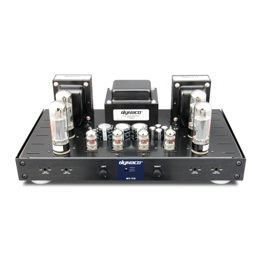
DYNACO ST-70 Panduan Perakitan - Halaman 7
Jelajahi secara online atau unduh pdf Panduan Perakitan untuk Penguat DYNACO ST-70. DYNACO ST-70 14 halaman. Driver 6gh8 ecf82 for the ab-q-st70 auto bias module
Juga untuk DYNACO ST-70: Instalasi dan Panduan Pengguna (9 halaman)

7. Remove 5/8 inch of insulation from the wire coming from pin #8 of the LEFT power takeoff. Run
this wire to V3. Slide the wire through pin # 1 (S) and into pin #8. You may have to twist either or
both pins slightly to line up the solder attachment holes. Attach one end of a 10 ohm bias
resistor (the four 10 ohm bias resistors are in with the VTA parts) to pin #8 of V3 (S). Connect
the other end of this resistor to the ground lug facing pin 8. (S)
8. Remove 5/8 inch of insulation from the wire coming from pin #4 of the LEFT power takeoff. Run
this wire to V2. Slide the wire through pin # 1 (S) and into pin #8. You may have to twist either or
both pins slightly to line up the solder attachment holes. Attach one end of a 10 ohm bias
resistor to pin #8 of V2 (S). Connect the other end of this resistor to the ground lug facing pin 8.
(S)
9. Remove 5/8 inch of insulation from the wire coming from pin #8 of the RIGHT power takeoff. Run
this wire to V6. Slide the wire through pin # 1 (S) and into pin #8. You may have to twist either or
both pins slightly to line up the solder attachment holes. Attach one end of a 10 ohm bias
resistor to pin #8 of V6 (S). Connect the other end of this resistor to the ground lug facing pin 8.
(S)
10. Remove 5/8 inch of insulation from the wire coming from pin #4 of the RIGHT power takeoff. Run
this wire to V7. Slide the wire through pin # 1 (S) and into pin #8. You may have to twist either or
both pins slightly to line up the solder attachment holes. Attach one end of a 10 ohm bias
resistor to pin #8 of V7 (S). Connect the other end of this resistor to the ground lug facing pin 8.
(S)
You will be making SEVENTEEN connections during the wiring to the VTA driver board
1. Connect the two input ground wires from the UNMARKED eyelets (these are two of the four
wires that you soldered in place in step 2 above) CLOSEST TO THE EDGE OF THE BOARD in the
center to the two grounding tabs on the input jacks. (S) Connect the wire coming from the "L-IN"
eyelet on the VTA board to the center tab of the LEFT input jack. (S) Connect the wire coming
from the "R-IN" eyelet on the VTA board to the center tab of the RIGHT input jack. (S)
2. Connect the two twisted pair of wires coming from V3 on the LEFT side of the amp to the two
open UNMARKED eyelets below the left tube socket on the bottom of the driver board. These
two UNMARKED eyelets are set at a about a 45 degree angle to each other. Shorten the wires to
the proper length (S)
3. Connect the two twisted pair of wires coming from V6 on the RIGHT side of the amp to the two
open UNMARKED eyelets below the right tube socket on the bottom of the driver board. These
two UNMARKED eyelets are set at a about a 45 degree angle to the sides of the board. Shorten
the wires to proper length (S)
4. If you have original Dynaco A-470 transformers then add about 12 inches of wire to each
YELLOW wire from each OUTPUT TRANSFORMER. (S). Insulate this connection. Shorten each
wire appropriately and connect the extended YELLOW wire from the LEFT OUTPUT
TRANSFORMER to the eyelet marked "NFB" on the LEFT side of the driver board. (S) Connect
the extended YELLOW wire from the RIGHT OUTPUT TRANSFORMER to the eyelet marked
"NFB" on the RIGHT side of the driver board. (S)
5. Connect a 2 ½ inch wire from pin #6 of V3 (S) to the UNMARKED eyelet near the left edge of the
driver board about 7/8 inch from the FRONT of the board. Do not press the wire in too deeply as
it may short against the chassis below. (S) Connect a 3 ½ inch wire from pin #6 of V2 (S) to the
