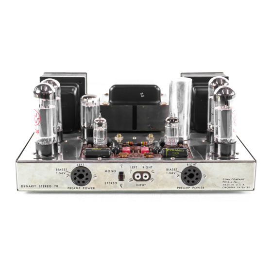
DYNACO Stereo 70 Petunjuk Untuk Perakitan - Halaman 8
Jelajahi secara online atau unduh pdf Petunjuk Untuk Perakitan untuk Penguat DYNACO Stereo 70. DYNACO Stereo 70 16 halaman. Series ii tube amplifier
Juga untuk DYNACO Stereo 70: Manual Pemulihan (20 halaman), Manual Pemulihan (5 halaman), Panduan Pemilik (12 halaman)

59
(t/f"
Con n e c t one end of a 10 ohm, (brown-
black-black),
I'
e sis tor to eyelet #8 (8).
Connect the other end to pin #3 of the left
power takeoff socket (8).
60 (,;/) Twist a pair of 3-1/2" wires together and
connect one pair of ends to eyelets #4 (8)
and # 5 (8). Connect the other pair of ends
to pins #1 (8) and #2 (8) of the left power
takeoff socket.
61 (vj Connect one end of a 2-1/2" wire to eyelet
#2 (8),
Connect the other end to pin #6 of
V3 (S).
62 (0 Connect one end of a 3-1/2" wire from
eyelet #1 (S).
Connect the other end to pin
#6 of V2 (8).
63 (I/) Connect one end of a 2-1/2" wire to eyelet
# 6 (S).
Connect the othe
I'
end to lug
#
2 of
the left potentiometer (S).
64 (V) Connect one end of an 8" wire to pin #4 of
V3 (8).
Connect the other end to eyelet
# 11 (8).
It is important to keep this wire
close to the chassis and carried around the
printed c i r cui t board, as shown in the
pictorial.
65
(0
Connect one end of a 5" wire to eyelet #9
(8).
Connect the other end to solder lug
near filter capacitor.
66 (r/) Connect one end of a 12" wire to lug # 1 of
the left screw terminal strip (S).
Connect
the other end to eyelet #12 (S).
See
pictorial.
67
("1
Connect one end of a 10-1/2" wire to lug
#4 (S) of the- teft screw terminal strip.
Connect the""'other end to the solder lug
near filter capacitor.
68
«(.))
Connect one end of a 9 -1/2" wire to lug # 1
of the right screw term ina 1 strip (S).
Connect the other end to eyelet # 13 (8). See
pictorial.
69 (e-j Connect one end of a 9" wire to lug # 4 (8)
of the right screw terminal strip.
Connect
the other end to solder lug near capacitor.
70
(v) Connect short link of wire from capacitor
ground lug (8) to solder lug near capacitor.
Solder all six wires which go to the pair of
solder lugs.
71 ( ) Insert the line cord through the grommet in
the rear of the chassis. Pull through about
five inches, tie a knot and then pull from
the outside till the knot is a g a ins t the
grommet.
Separate the two conductors of
6
the line cord to the knot then strip about
1/2" of insulation from each end.
Connect
one end to lug B of the fuse post (S).
Con-
neet the othe
I'
end to lug # 2 of the on -off
switch (S).
This completes the wiring of
your amplifier.
It
is wise to go back and check all connec-
tions for correctness and for good solder-
ing. All hardware should also be checked
for tightness.
The fuse can now be
in-
stalled in the fuse post on the rear of the
chassis. The four rubber feet should then
be pushed into the four holes in the bottom
plate - from outside tow a
I'
d inside and
seated with a twisting motion.
INITIAL ADJUSTMENT
Plug in the EL-34 tubes V2, V3, V6 and V7.
Also plug the 7199 tubes into pI' in ted circuit
sockets. Do not plug in GZ-34 rectifier tube. If
an
0
h m met e
I'
is available, measure resistance
from capacitor lug #2 to ground. This should be
in excess of one hundred thousand ohms. Inspect
wiring to make sure that all joints are soldered
and that no parts are shorting together.
Plug line
cord into 117 volt ac line and turn on switch.
While tubes are warming up, set the bias adjusting
potentiometers to the c en tel' of their rotation.
This is approximately the correct setting and can
serve as an emergency operating adjustment if no
test instruments a I' e available.
(H
0
WE V E R,
OPERATION WITHOUT CORRECT BIAS ADJUST-
MENT 18 NOT RECOMMENDED A8 IT RE8ULT8
IN POOR PERFORMANCE AND PROBABLE
DAMAGE TO COMPONENTS.)
Your D y n a kit includes Dyna Biaset (patent
pending) which greatly simplifies setting of the
bias voltage. This can now be done with the most
simple and inexpensive types of dc meters as long
as they have a rating of 1000 ohms per volt or
higher. The correct setting of the bias provides a
total cathode current for each pair of EL-34 tubes
of 100 mao
This current through the precision
15.6 ohm resistors produces a voltage drop of
exactly 1. 56 volts dc, and this v
0
It
age can be
checked at pin #8 of each preamplifier power take-
off socket.
1. 56 volts is also the voltage which is
furnished by a "0" type flashlight dry cell .. Thus
any fresh cell of this type can be used for an
accurate reference standard for bias setting.
The procedure for setting the bias is to meas-
ure the voltage output of a "D" type dry cell and
note the meter reading. Then insert the positive
meter probe in the pin #8 hole of the left pream-
plifier power socket (note that outside the chassis
the pin n u m bel's are counted counterclockwise
from the keyway while inside the chassis they are
counted clockwise).
The negative met e r probe
