Great Power Engine GP-61 Buku Petunjuk - Halaman 7
Jelajahi secara online atau unduh pdf Buku Petunjuk untuk Mesin Great Power Engine GP-61. Great Power Engine GP-61 14 halaman.
Juga untuk Great Power Engine GP-61: Panduan Pemilik (10 halaman)
machines and therefore must not be used. Do not use mixed fuel that is more than 90 days old. GP does
not take responsibility for any damage resulted from using low-quality fuel.
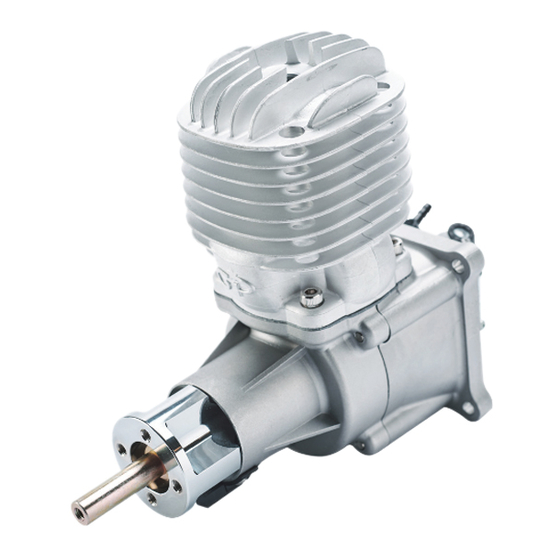
ENGINE INSTALLATION
Screw: You can directly mount the engine on the firewall. We recommend M6 screws for your GP
1.
engine. The firewall should be stiff enough to prevent engine vibrations. Use high-grade 1/4 bolts
with washers and locknuts in the back of the firewall. Make sure your firewall is structurally sound.
Servo: We recommend a high-quality servo for the throttle, as it can ensure accurate and reliable
2.
throttle operation. We also recommend a high-quality servo linkage. Do not use metallic servo
linkages, because this could cause radio interference.
Fuel Tank: We recommend a 450cc~500cc fuel tank for GP61, 600cc~800cc for GP76,
3.
800cc~1000cc for GP123/GP88, and 1500cc for GP178. The tank must be vented and routed to
the outside of the plane, preferably to the bottom of the cowl.
Cooling: Proper air circulation under the cowl must be ensured because cooling is critical to
4.
engine's performance and longevity. To cool the engine, an appropriately-sized air intake is
required. The exhaust outlet should be 3 times larger than the intake. Make sure cool air goes
through cylinder fins and does not bypass them to take an easy route to the exit. It is better to build
baffles because they can create turbulent air movements in the cylinder fins, which results in
maximum cooling for an air-cooled engine.
Caution: It is important to use seals to prevent sawdust, residual abrasives etc. from entering
5.
engine interior through the openings when engine is being mounted in the model. Keep the fuselage
interior clean and make sure that all parts are tightly placed so that they will not get drawn into the
engine.
END POINT ADJUSTMENT
L1=L2 and x°=y°
6