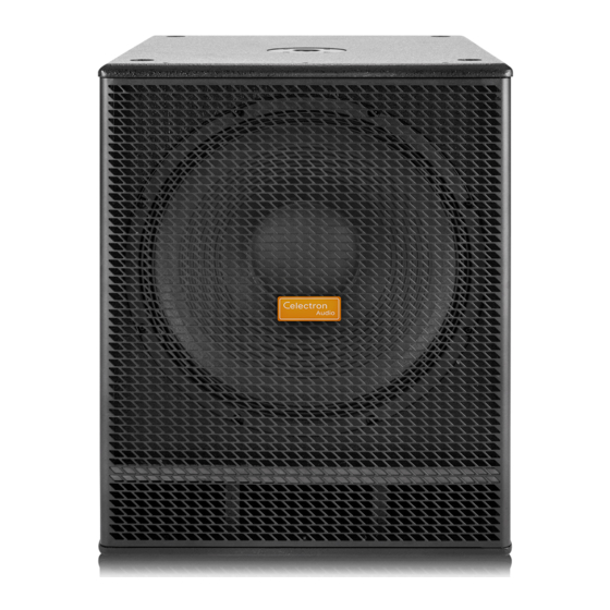
Celectron Audio SW118A Panduan Pengguna - Halaman 14
Jelajahi secara online atau unduh pdf Panduan Pengguna untuk Subwoofer Celectron Audio SW118A. Celectron Audio SW118A 16 halaman.

GENERAL INFORMATION
Thank you for having chosen a CELECTRON product.
The SW Series is a range of sub-woofers designed to complement CELECTRON full-range passive or ac ve speakers. The
variety of size, power and SPL offered by the five SW models provides the perfect low extension solu on for any
speaker model available in the CELECTRON range.
All the SW models feature large VC woofers and band-pass or vented design, which provide very 'punchy', dynamic lows
together with an extended low frequency response.
The CLASS D amplifier modules can generate a massive amount of con nuous power in a compact and reliable package.
All the modules include a STEREO pre-amp sec on, 24dB/oct. crossover filters with selectable frequency and PHASE
reverse switch. The SW110A cabinet is built with 15 plywood and feature metal handle for an easy transport.
INSTRUCTIONS ( FIG. 1 / 2 / 3 )
1. INPUT LEFT (combo XLR-JACK input)
This is a female combo connector, which accepts a XLR or a JACK plug from almost any type of equipment with a
balanced or unbalanced line level outputs. The XLR input is wired as follows:
Pin 1 = shield or ground
Pin 2 = + posi ve or "hot"
Pin 3 = - nega ve or "cold"
The JACK input is wired as follows:
Tip = + posi ve or "hot"
Ring = - nega ve or "cold"
Sleeve = shield or ground
When connec ng an unbalanced signal, wire them as follows:
Pin2 / Tip = + posi ve or "hot"
Pin 1-3 / Sleeve = shield or ground
NOTE: Whenever possible, use always balanced cables. Unbalanced lines may also be used but may result in noise over
long cable runs. In any case, avoid using a balanced cable for one channel and an unbalanced one for the other.
2. LINK LEFT (XLR output balanced)
This is a male XLR connector, that is connected in parallel with the respec ve line input (so the LINK is wired as the
input). Connect these to the inputs of other powered speakers to make an array.
3. OUT LEFT (XLR output balanced)
This is a male XLR connector, that provides a balanced line-level signal. This signal is fi ltered with an high-pass fi lter to
connect a sat speaker. This output is wired as follows:
Pin 1 = shield or ground
Pin 2 = + posi ve or "hot"
Pin 3 = - nega ve or "cold"
4. INPUT RIGHT (combo XLR-JACK input)
Same as above. Use both inputs and outputs when connect a stereo system to a single subwoofer (1 sub + 2 sat). In the
case of mono system (1 sub + 1 sat for each channel) you can use either le or right input without dis nc on.
5. LINK RIGHT (XLR output balanced)
This is a male XLR connector, that is connected in parallel with the respec ve line input (so the LINK is wired as the
input). Connect these to the inputs of other powered speakers to make an array.
6. OUT RIGHT (XLR output balanced)
Same as above. Use both inputs and outputs when connec ng a stereo system to a single subwoofer (1 sub + 2 sat).
In the case of mono system (1 sub + 1 sat for each channel) you have to use the same channel used for input: le or
right.
7. GND LIFT switch
This switch li s the ground of the balanced audio inputs from the earth-ground of the amplifi er. If you have HUM
noise problems on one or more loudspeaker try to change the posi on of these switches (o en all up or all down for
all the amplifi ers in the system). Please note that to have an eff ect all cables must be balanced.
8. FILTER switch
Use this switch to set the crossover frequency for the internal filter and for the OUT LEFT and RIGHT connectors.
Choose the crossover frequency by your taste or music genre.
12
